
Reinforcement of Welded Branch Connection
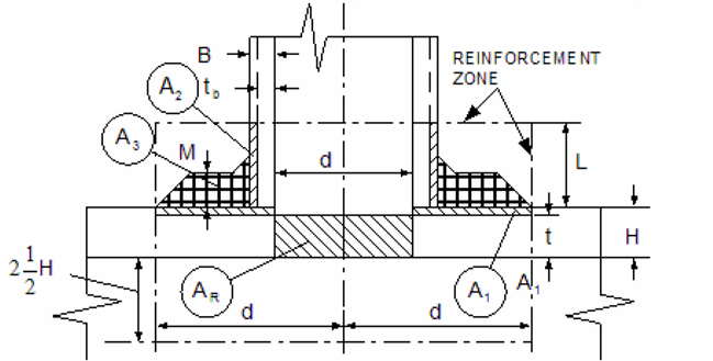
One of the first methods of providing branch connections was to stub a branch line into a run. Sometimes a pad would also be used to reinforce the connections. The figure below shows a header with pad-reinforced branch connections. Although tees and extrusions have generally taken the place of reinforced branch connections, an example calculation is presented for the occasional instance where the designer may want to use this type of connection.
Nomenclature:
Refer to figure for a physical representation of the applicable terms.
𝐴𝑅 = (𝑡𝑟𝐷𝑜), Required reinforcement area
𝐴𝑝 = 𝐴1 + 𝐴2 + 𝐴3, Required reinforcement area of
𝐴1 = 𝐷𝑜(𝑇𝑟 − 𝑡𝑟), The area lying within the reinforcement zone resulting from any excess thickness available in the run wall.
𝐴2 = 2𝐿(𝑇𝑏 − 𝑡𝑏), The area lying within the reinforcement zone resulting from any excess thickness available in the branch pipe.
𝐴3 = 𝑡𝑝(𝑑𝑝 − 𝑑), The area lying within the reinforcement zone resulting from the addition of a pad of branch reinforcement member.
𝑑 = Outside diameter of branch pipe(in)
𝑑𝑐 = Corroded internal diameter of branch pipe(in)
𝑑𝑝 = Outside diameter of the reinforcement pad(in)
𝐷 = Outside diameter of run(in)
𝐷𝑐 = Corroded internal diameter of run(in)
𝐷𝑜 = Corroded internal diameter of extruded outlet measured at the level of outside surface of run(in)
𝐸 = Longitudinal Joint Factor
𝐹 = Design Factor
𝑇 = Temperature derating factor
𝐿 = Height of the reinforcement zone.
L is the lesser of: (1). 2.5 𝑇𝑏 + 𝑡𝑝 or (2). 2.5𝑇𝑟
𝑃 = Design pressure of the branch connection
𝑆 = Yield strength of the component being considered(i.e. run, branch, pad)
𝑡𝑏 = The required thickness of the branch pipe according to the steel pipe design formula,  but not including any thickness for corrosion.
𝑇𝑏 =Actual thickness of the run wall, not including corrosion allowance(in)
𝑡𝑟 = The required thickness of run according to the steel pipe design formula,  , but not including any thickness for corrosion.
𝑇𝑟 = Actual thickness of the run wall, not including corrosion allowance
𝑡𝑝 = The required thickness of the reinforcing pad
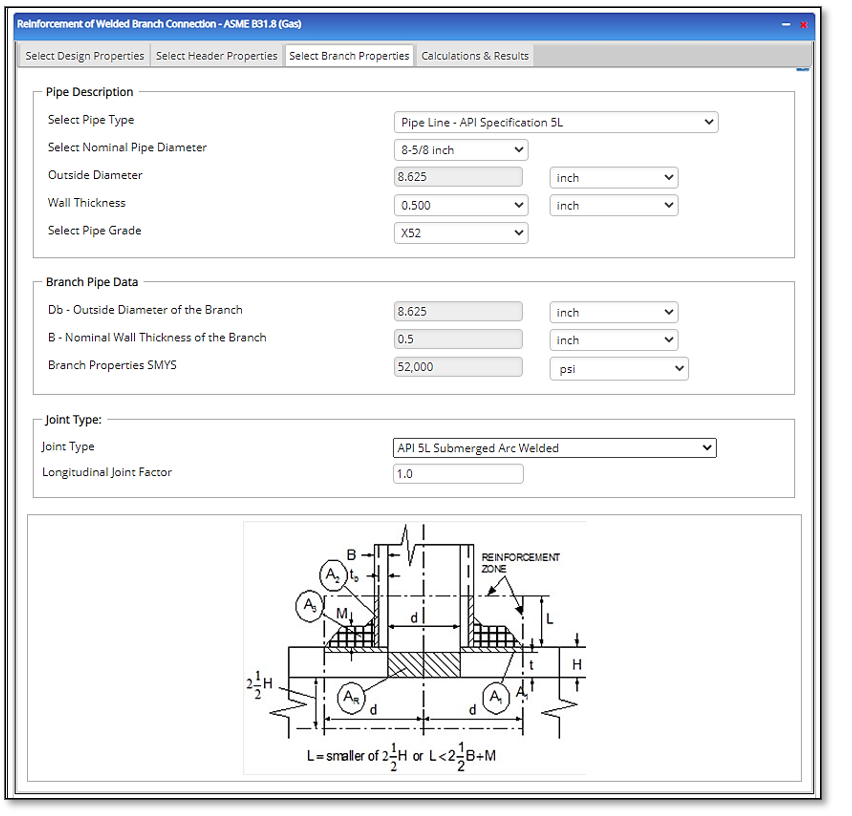
Input Parameters
- To create a new case, click the “Add Case” button
- Select the Reinforcement application from the Pipeline Facilities section.
- Enter Case Name, Location, Date and any necessary notes.
- Fill out all required fields.
- Make sure the values you are inputting are in the correct units.
- Click the CALCULATE button.
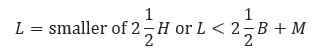
- Design Properties
- Design Factor F
- Temperature Deration Factor T
- Operating Pressure
- F- Design Factor
- T – Temperature Derating Factor
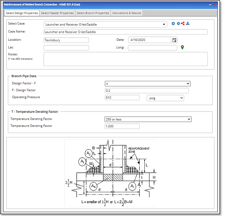
- Header Properties
- M – Thickness of the added reinforcement
- D – Outside Diameter of the Header
- H- Nominal Wall thickness of the Header
- Specified Minimum Yield Strength
- E- Longitudinal Joint Factor
- Branch Properties
- Db – Outside Diameter of the Branch
- B – Nominal Wall thickness of the Branch
- Specified Minimum Yield Strength
- E- Longitudinal Joint Factor
- Minimum Reinforcement Outside Data
- Reinforcement SMYS
- Distance through the Electrolyte Traveled by the Current(cm)
- Cross Sectional Area through which the Current Flows (sq. cm)
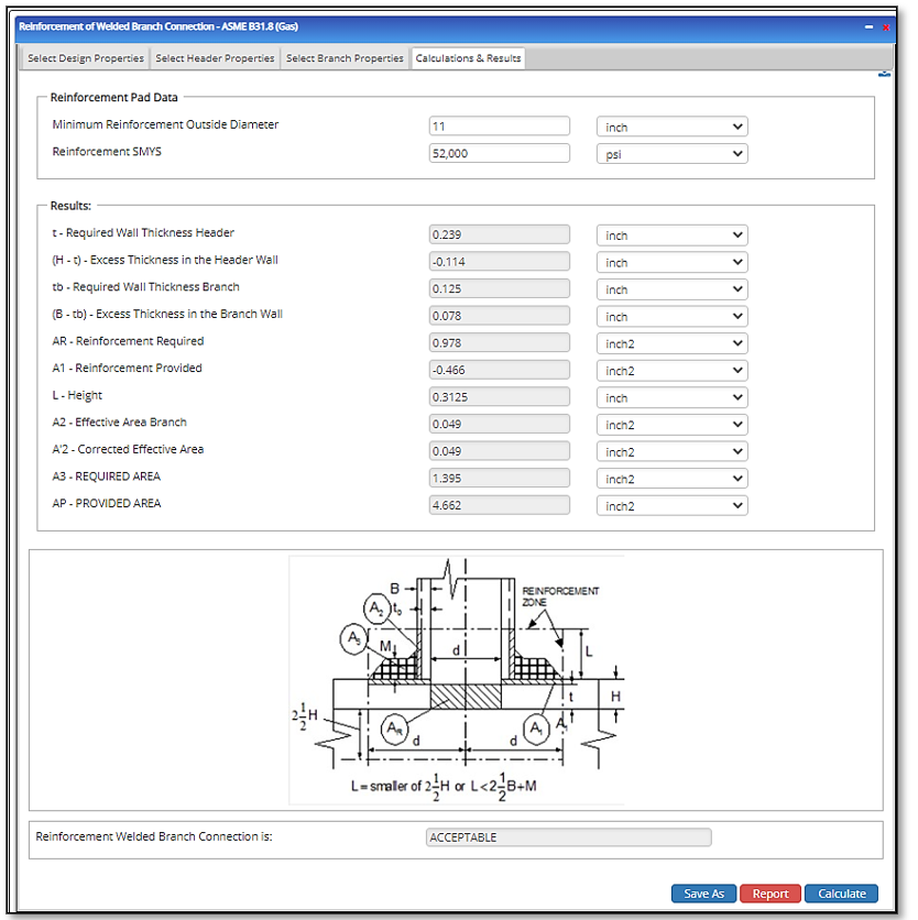
Outputs/Reports
- View the results.
- If an input parameter needs to be edited be sure to hit the CALCULATE button after the change.
- To SAVE, fill out all required case details then click the SAVE button.
- To rename an existing file, click the SAVE As button. Provide all case info then click SAVE.
- To generate a REPORT, click the REPORT button.
- The user may export the Case/Report by clicking the Export to Excel/PowerPoint icon.
- To delete a case, click the DELETE icon near the top of the widget.
- t – Required Wall Thickness of the Header
- (H – t) – Excess Thickness in the Header Wall
- tb – Required Wall Thickness of the Branch
- (B – tb) – Excess Thickness in the Branch Wall
- AR – Reinforcement Required
- A1 – Reinforcement Provided
- L – Height
- A2 – Effective Area in Branch/Outlet
- A2 – Corrected Effective Area
- A3 – REQUIRED AREA
- AP – PROVIDED AREA
Related Links
Table of Contents
Table of Pages
Table of Contents
- Pipeline HUB User Resources
- AC Mitigation PowerTool
- API Inspector's Toolbox
- Horizontal Directional Drilling PowerTool
- Crossings Workflow
- Hydrotest PowerTool
- Pipeline Toolbox
- Encroachment Manager
- PRCI AC Mitigation Toolbox
- PRCI RSTRENG
- RSTRENG+
- Ad-hoc Analysis
- Database Import
- Data Availability Dashboard
- ESRI Map
- Report Builder
- Crossings Workflow
- Hydrotest PowerTool
- Investigative Dig PowerTool
- Hydraulics PowerTool
- External Corrosion Direct Assessment Procedure - RSTRENG
- Canvas
- Definitions
- Pipe Schedule and Specifications Tables