
Relief Valve: Reactive Force
This calculation determines the force at the point of discharge of a pressure relieving device. API 520 indicates that the equation is for elbow and vertical exhaust pipe.
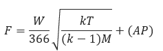
where
𝐹 − Reactive force at the point of discharge to the atmosphere(lbf)
𝑊 − Flow of gas(lbm/hr)
𝑀 − Molecular Weight of Gas
𝐴 = Area of outlet at the point of discharge(in2)
𝑇 − Temperature at outlet(°R)
𝑘 − Specific Heat Ratio (𝐶𝑃/𝐶𝑣) at the outlet conditions
P − Static pressure within the outlet at the pint of discharge(psig)
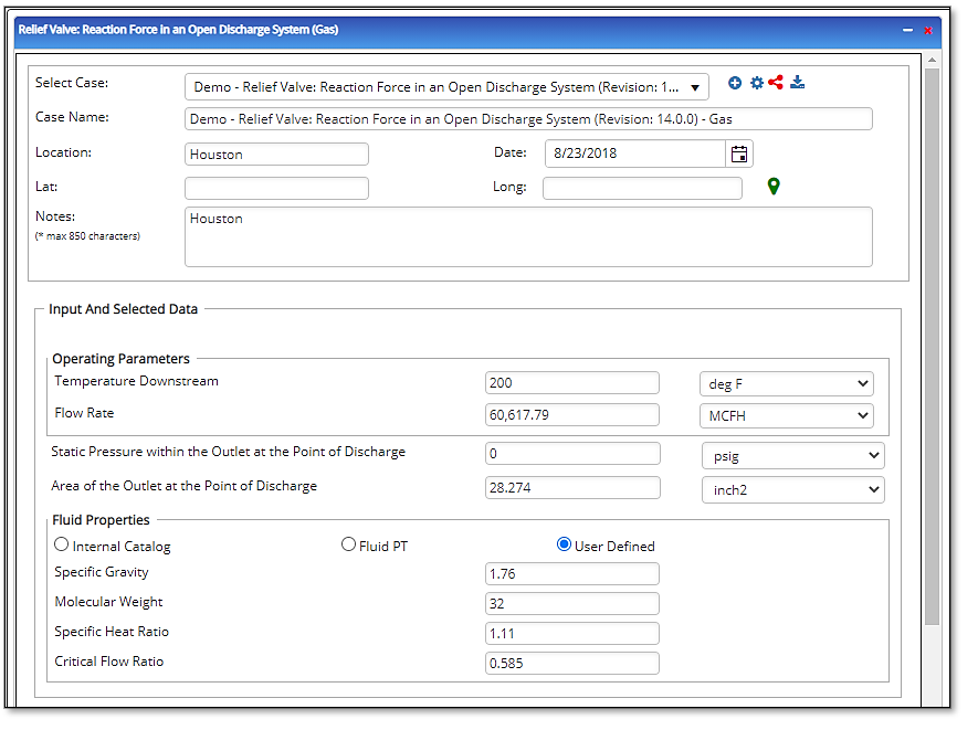
Input Parameters
- To create a new case, click the “Add Case” button
- Select the Relief Valve Reactive Force application from the Pipeline Facilities section.
- Enter Case Name, Location, Date and any necessary notes.
- Fill out all required fields.
- Make sure the values you are inputting are in the correct units.
- Click the CALCULATE button.
- Relief Valve Set Pressure (psig)
- Gas or Vapor Flowing Temperature (F)
- Back Pressure (psig)
- Required Flow through Valve (MSCFH)
- Kd – Effective Coefficient of Discharge
- Kb – Capacity Correction Factor
- Compressibility Factor of Gas or Vapor
- Molecular Weight of Gas or Vapor
- Specific Heat Ratio
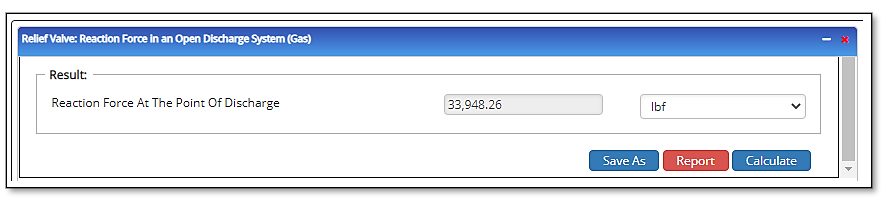
Outputs/Reports
- View the results.
- If an input parameter needs to be edited be sure to hit the CALCULATE button after the change.
- To SAVE, fill out all required case details then click the SAVE button.
- To rename an existing file, click the SAVE As button. Provide all case info then click SAVE.
- To generate a REPORT, click the REPORT button.
- The user may export the Case/Report by clicking the Export to Excel/PowerPoint icon.
- To delete a case, click the DELETE icon near the top of the widget.
- t – Required Wall Thickness of the Header
- (H – t) – Excess Thickness in the Header Wall
- tb – Required Wall Thickness of the Branch
- (B – tb) – Excess Thickness in the Branch Wall
- AR – Reinforcement Required
- A1 – Reinforcement Provided
- L – Height
- A2 – Effective Area in Branch/Outlet
- A2 – Corrected Effective Area
- A3 – REQUIRED AREA
- AP – PROVIDED AREA
- Reinforcement of Welded Branch Connection is:
Related Links
Table of Contents
Table of Pages
Table of Contents
- Pipeline HUB User Resources
- AC Mitigation PowerTool
- API Inspector's Toolbox
- Horizontal Directional Drilling PowerTool
- Crossings Workflow
- Hydrotest PowerTool
- Pipeline Toolbox
- Encroachment Manager
- PRCI AC Mitigation Toolbox
- PRCI RSTRENG
- RSTRENG+
- Ad-hoc Analysis
- Database Import
- Data Availability Dashboard
- ESRI Map
- Report Builder
- Crossings Workflow
- Hydrotest PowerTool
- Investigative Dig PowerTool
- Hydraulics PowerTool
- External Corrosion Direct Assessment Procedure - RSTRENG
- Canvas
- Definitions
- Pipe Schedule and Specifications Tables