
Relief Valve Sizing For Gas or Vapor
Critical Flow Behavior
If a compressible gas is expanded across a nozzle, an orifice, or the end of a pipe, its velocity and specific volume increase with decreasing downstream pressure. For a given set of upstream conditions (using the example of a nozzle), the mass rate of flow through the nozzle will increase until a limiting velocity is reached in the throat. It can be shown that the limiting velocity is the velocity of sound in the flowing media at that location. The flow rate that corresponds to the limiting velocity is known as the critical flow rate.
The absolute pressure ratio of the pressure in the throat at sonic velocity (𝑃𝑐𝑓) to inlet pressure (𝑃1) is called critical pressure ratio.(𝑃𝑐𝑓) is known as the critical flow pressure. Under critical flow conditions, the actual pressure in the throat cannot fall below the critical flow pressure even if a much lower pressure exists downstream. At critical flow, the expansion from throat pressure to downstream pressure takes place irreversibly with energy dissipated in turbulence into the surrounding fluid.
The critical flow pressure ratio in absolute units may be estimated using the ideal gas relationship in the equation below.
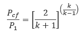
Where
𝑃𝑐𝑓 − Critical flow throat pressure(lb/in2)
𝑃1 = Upstream relieving pressure(lb/in2)
𝑘 − ratio of specific heats for an ideal
The sizing equations for pressure relief valves in vapor or gas service fall into two general categories depending on whether the flow is critical or subcritical.
If the pressure downstream of the throat is less than or equal to the critical flow pressure, (𝑃𝑐𝑓), then critical flow will occur, and the procedures in SIZING FOR CRITICAL FLOW should be applied.
If the downstream pressure exceeds the critical pressure, (𝑃𝑐𝑓), then subcritical flow will occur, and procedure in SIZING FOR SUBCRITICAL FLOW should be applied.
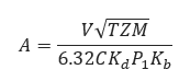
Where
𝐴 − required effective discharge area of the valve(in2)
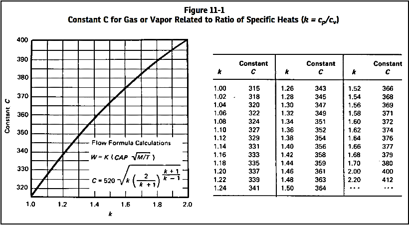
𝐶 − coefficient determined from an expression of the ratio of the specific heats at standard conditions
𝐾𝑑 − effective coefficient of discharge (use 0.975 for this eq.)
𝑃1 = Upstream relieving pressure(lb/in2)
𝐾𝑏 − capacity correction factor due to back pressure
T− relieving temperature of the inlet gas or vapor(°R)
𝑍 − compressibility factor for the deviation of the actual gas from a perfect gas, a ratio evaluated at inlet conditions
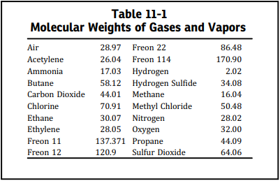
𝑀 − molecular weight of the gas or vapor
𝑉 − required flow through the valve(ft3/min) at 14.7
𝐺 − specific gravity of gas referred to air = 1.00 for air at 14.7 (lb/in2) absolute and 60℉
The value of the coefficient C can be evaluated from the expression of the ratio of the specific heats of the gas or vapor. The ratio of specific heats of any ideal gas and possibly the ratio of specific heats of a diatomic actual gas can be found in any acceptable reference work. When k cannot be determined, it is suggested that C = 315
When the ratio of back pressure to inlet pressure exceeds the critical pressure ratio (𝑃𝑐𝑓– 𝑃1) the flow through the pressure relief valve is subcritical. This equation may be used to calculate the required effective discharge area for a conventional relief valve that has its spring setting adjusted to compensate for superimposed back pressure and for sizing a pilot-operated relief valve.
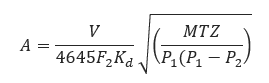
Where
𝐴 − required effective discharge area of the valve(in2)
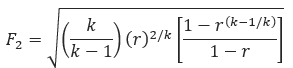
𝐹2 − coefficient of subcritical
𝐾𝑑 − effective coefficient of discharge
𝑃1 = Upstream relieving pressure(lb/in2)
𝑃2 = back pressure(lb/in2)
𝑘 − ratio of the specific heats
T − relieving temperature of the inlet gas or vapor(°R)
𝑍 − compressibility factor for the deviation of the actual gas from a perfect gas, a ratio evaluated at inlet conditions
𝑀 − molecular weight of the gas or vapor
𝑉 − required flow through the valve(ft3/min) at 14.7
𝐺 − specific gravity of gas referred to air=1.00 for air at 14.7 (lb/in2)absolute and 60℉
The value of the coefficient C can be evaluated from the expression of the ratio of the specific heats of the gas or vapor. The ratio of specific heats of any ideal gas and possibly the ratio of specific heats of a diatomic actual gas can be found in any acceptable reference work. When k cannot be determined, it is suggested that C = 315
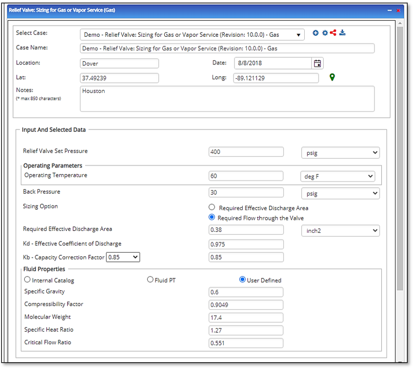
Input Parameters
- To create a new case, click the “Add Case” button
- Select the Relief Valve Sizing for Gas or Vapor application from the Pipeline Facilities section.
- Enter Case Name, Location, Date and any necessary notes.
- Fill out all required fields.
- Make sure the values you are inputting are in the correct units.
- Click the CALCULATE button.
- Molecular Weight
- Specific heat Ratio
- Critical Flow Ratio
- Relief Valve Set Pressure(psig)
- Gas or Vapor Flowing Temperature(°F)
- Back Pressure(psig)
- Required Flow Through Valve(MSCFH)
- kd – Effective Coefficient of Discharge
- Kb – Capacity Correction Factor
- Compressibility Factor of Gas/Vapor
- Specific Gravity of Gas/Vapor
- Specific Heat Ratio
- Required Effective Discharge Area
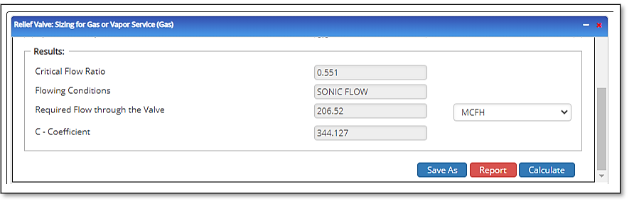
Outputs/Reports
- View the results.
- If an input parameter needs to be edited be sure to hit the CALCULATE button after the change.
- To SAVE, fill out all required case details then click the SAVE button.
- To rename an existing file, click the SAVE As button. Provide all case info then click SAVE.
- To generate a REPORT, click the REPORT button.
- The user may export the Case/Report by clicking the Export to Excel/PowerPoint icon.
- To delete a case, click the DELETE icon near the top of the widget.
- Critical Flow Ratio
- Flowing Conditions:
- Required Effective Discharge Area(in²)
- C – Coefficient
Related Links
Table of Contents
Table of Pages
Table of Contents
- Pipeline HUB User Resources
- AC Mitigation PowerTool
- API Inspector's Toolbox
- Horizontal Directional Drilling PowerTool
- Crossings Workflow
- Hydrotest PowerTool
- Pipeline Toolbox
- Encroachment Manager
- PRCI AC Mitigation Toolbox
- PRCI RSTRENG
- RSTRENG+
- Ad-hoc Analysis
- Database Import
- Data Availability Dashboard
- ESRI Map
- Report Builder
- Crossings Workflow
- Hydrotest PowerTool
- Investigative Dig PowerTool
- Hydraulics PowerTool
- External Corrosion Direct Assessment Procedure - RSTRENG
- Canvas
- Definitions
- Pipe Schedule and Specifications Tables