
Pump Station Piping – Pipe Wall Thickness
Pipe wall thickness (WT) is based pipe diameter, SMYS, internal design pressure/factor, joint factor and sum of allowance WT.
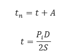
𝑡𝑛 − Nominal Wall Thickness />Satisfying Requirements for Pressure and Allowances [in]
𝑡 − Pressure Design Wall Thickness [in]
𝐴 − Sum of Allowances for Threading and Grooving
𝑃𝑖 − Internal Design Gauge Pressure [psig]
𝐷 − Outside Pipe Diameter [in]
𝑆 − Applicable Allowable Stress Value [psi]
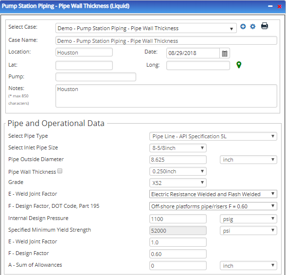
Input Parameters
- To create a new case, click the “Add Case” button
- Select the Pump Specific Speed application from the Pipeline Pumps module.
- Enter Case Name, Location, Date and any necessary notes.
- Fill out all required fields.
- Make sure the values you are inputting are in the correct units.
- Click the CALCULATE button
- Nominal Pipe Size [in]
- Pipe Grade (if pipe grade is unknown use Grade A 24000)
- Wall Thickness [in]
- E – Longitudinal Joint Factor
- F – Design Factor
- Internal Design Pressure [psi]
- A – Sum of Allowances [in]
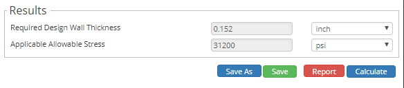
Outputs/Reports
- View the results.
- If an input parameter needs to be edited be sure to hit the CALCULATE button after the change.
- To SAVE, fill out all required case details then click the SAVE button.
- To rename an existing file, click the SAVE As button. Provide all case info then click SAVE.
- To generate a REPORT, click the REPORT button.
- The user may export the Case/Report by clicking the Export to Excel/PowerPoint icon.
- To delete a case, click the DELETE icon near the top of the widget.
- Required Design Wall Thickness [in]
- Applicable Allowable Stress [psi]
Related Links
Table of Contents
Table of Pages
Table of Contents
- Pipeline HUB User Resources
- AC Mitigation PowerTool
- API Inspector's Toolbox
- Horizontal Directional Drilling PowerTool
- Crossings Workflow
- Hydrotest PowerTool
- Pipeline Toolbox
- Encroachment Manager
- PRCI AC Mitigation Toolbox
- PRCI RSTRENG
- RSTRENG+
- Ad-hoc Analysis
- Database Import
- Data Availability Dashboard
- ESRI Map
- Report Builder
- Crossings Workflow
- Hydrotest PowerTool
- Investigative Dig PowerTool
- Hydraulics PowerTool
- External Corrosion Direct Assessment Procedure - RSTRENG
- Canvas
- Definitions
- Pipe Schedule and Specifications Tables