
Regulator & Station Piping Sizing
Sizing of regulator is performed using Universal Gas Equation:
1. For Subsonic Flow
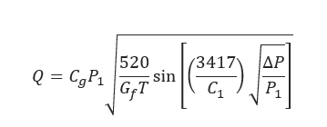
𝑄 = Gas Flowrate,[scf/h]
𝐺𝑓 = Gas Specific Gravity
𝑇 = Absolute Temperature,[°R]
𝐶𝑔 = Gas Sizing Coefficient
𝐶𝑣 = Liquid Sizing Coefficient
𝐶1 = ![]()
𝑃1 = Gas Sizing Coefficient
∆𝑃 = 𝑃1 − 𝑃2 − Differential Pressure Across Valve
𝑃2 = Outlet Pressure, [psia]
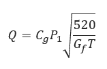
2. For Sonic Flow equation is reduced to:
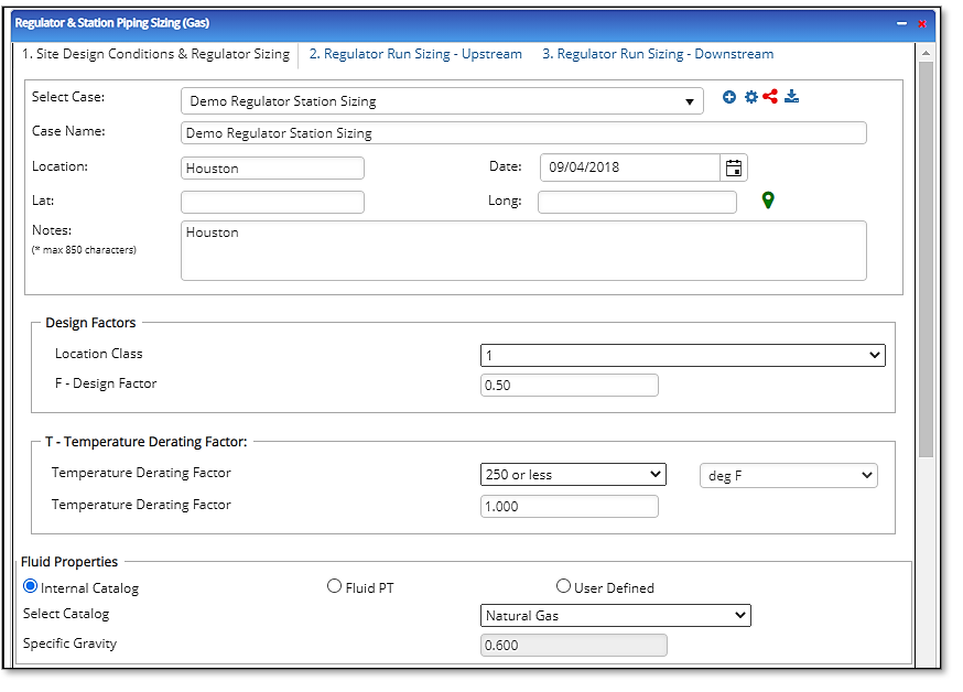
Input Parameters
- To create a new case, click the “Add Case” button
- Select the Regulator & Station Piping Sizing application from the Regulators & Meters module list.
- Enter Case Name, Location, Date and any necessary notes.
- Fill out all required fields.
- Make sure the values you are inputting are in the correct units.
- Click the CALCULATE button.
- Class Location
- Temperature
- F – Design Factor
- T – Temperature Derating Factor
- Gas Specific Gravity
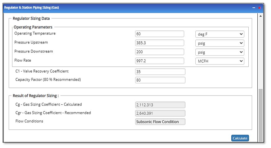
- Regulator Sizing Data
- P1 – Inlet Pressure
- P2 – Outlet Pressure
- Q – Flow Rate
- Gas Specific Gravity
- Flowing Gas Temperature
- C1 – Valve Recovery Coefficient
- Capacity Factor (80% Recommended)
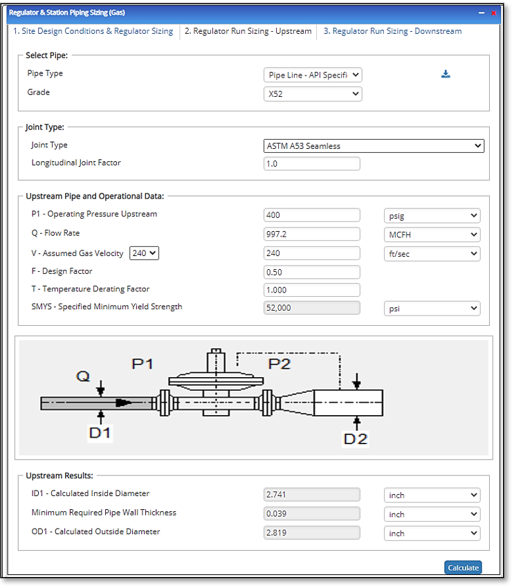
- Upstream Pipe and Operational Data
- P1 – Operating Pressure – Upstream
- Q – Flow Rate
- V – Assumed Gas Velocity
- F – Design Factor
- T – Temperature Derating Factor
- SMYS – Specified Minimum Yield Strength
- E – Longitudinal Joint Factor
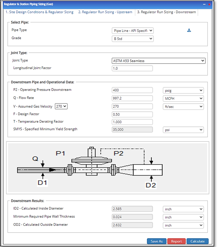
- Downstream Pipe Operational Data
- P2 – Operating Pressure – Downstream
- Q – Flow Rate
- V – Assumed Gas Velocity
- F – Design Factor
- T – Temperature Derating Factor
- SMYS – Specified Minimum Yield Strength
- E – Longitudinal Joint Factor
Outputs/Reports
- View the results.
- If an input parameter needs to be edited be sure to hit the CALCULATE button after the change.
- To SAVE, fill out all required case details then click the SAVE button.
- To rename an existing file, click the SAVE As button. Provide all case info then click SAVE.
- To generate a REPORT, click the REPORT button.
- The user may export the Case/Report by clicking the Export to Excel/PowerPoint icon.
- To delete a case, click the DELETE icon near the top of the widget.
- Regulator Sizing Results
- Cg – Gas Sizing Coefficient – Calculated
- Cgr – Gas Sizing Coefficient – Recommended
- Flow Conditions:
- Upstream Results
- ID1 – Calculated Inside Diameter
- Minimum Required Pipe Wall Thickness
- OD1 – Calculated Outside Diameter
- Downstream Results
- ID1 – Calculated Inside Diameter
- Minimum Required Pipe Wall Thickness
- OD1 – Calculated Outside Diameter
Related Links
Table of Contents
Table of Pages
Table of Contents
- Pipeline HUB User Resources
- AC Mitigation PowerTool
- API Inspector's Toolbox
- Horizontal Directional Drilling PowerTool
- Crossings Workflow
- Hydrotest PowerTool
- Pipeline Toolbox
- Encroachment Manager
- PRCI AC Mitigation Toolbox
- PRCI RSTRENG
- RSTRENG+
- Ad-hoc Analysis
- Database Import
- Data Availability Dashboard
- ESRI Map
- Report Builder
- Crossings Workflow
- Hydrotest PowerTool
- Investigative Dig PowerTool
- Hydraulics PowerTool
- External Corrosion Direct Assessment Procedure - RSTRENG
- Canvas
- Definitions
- Pipe Schedule and Specifications Tables