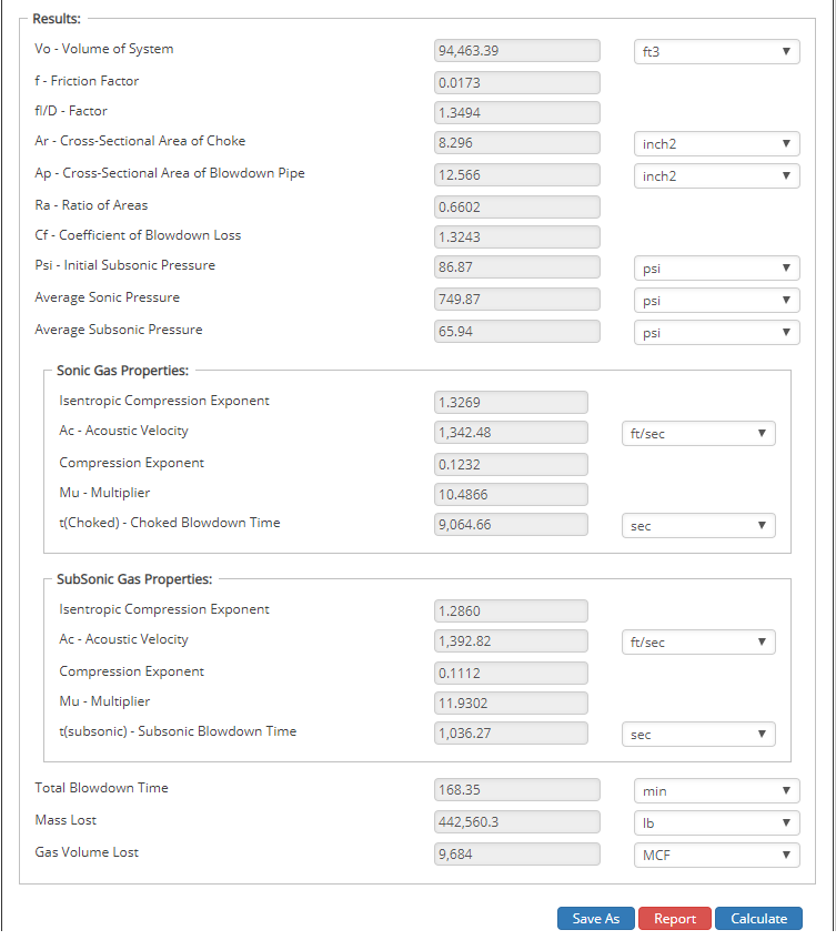
Gas Pipeline Blowdown - Semiemperical Model - Report No. 87-2
Based on SW Research Report calculations for the blowdown time and mass of gas vented to atmosphere to a piping system. Accurate to within a few percent. Blowdown time is impacted through constricting valve changes from sonic (choked) flow to subsonic. This is because of the pressure ratio across the valve is unknown.
Where
𝑉𝑜 − Total Volume[ft3]
𝑉𝑠𝑦𝑠 − Volume of system[ft3]

𝑉𝑃 − Volume of Mainline Pipe[ft3]
𝐿𝑝 − Mainline Pipe Length[in]
𝐷𝑝𝑖 − Mainline Pipe Internal Diameter[in]

𝑉𝑠(𝑖) − Volume of individual pipes[ft3]
𝐷𝑠(𝑖) − Diameter of individual pipes[in]
𝑤𝑡𝑠(𝑖) − Wall Thickness of individual pipes[in]
𝐿𝑠(𝑖) − Length of individual pipes[mi]

𝑓 − Friction Factor(Sum of flow friction through all diameters of blowdown piping)
𝐿 − Blowdown Pipe Length[ft]
𝑑𝑖 − Internal Diameter of Blowdown Pipe[in]

𝐴𝑟 − Cross−Sectional Area of Choke[in2]
𝐷𝑟 − Diameter of Choked Flow Point[in]

𝐴𝑝 − Cross−Sectional Area of Blowdown Pipe[in2]
𝑑𝑖 − Internal Diameter of Blowdown Pipe[in]

𝑅𝐴 − Ratio of Choked Flow Area to Pipe Flow Area
𝑐𝑓 − Coefficient of Blowdown Loss(Sum of loss for 𝑅𝐴/𝑓𝑙𝑑)
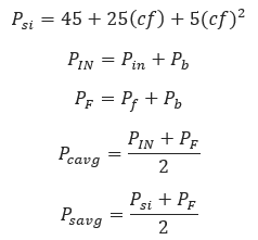
𝑃𝑠𝑖 − Initial Subsonic Pressure[psi]
𝑃𝑖𝑛 − Initial Pressure[psi]
𝑃𝑓 − Final Pressure[psi]
𝑃𝑏 − Base Pressure[psi]
𝑃𝑐𝑎𝑣𝑔 − Average Sonic Pressure[psi]
𝑃𝑠𝑎𝑣𝑔 − Average Subsonic Pressure[psi]
From the SWRI – SIMPLIFIED BLOWDOWN CALCULATIONS FOR PRESSURIZED GAS SYSTEMS Technical Report you can find tables and equations to complete many of the remaining calculations in this module.
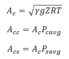
𝛾 − Can be found in table I of the SWRI Technical report mentioned above.
𝑅 − Universal gas constant (𝑈𝑟 = 1545)divided by the molecular weight 𝑀𝑤
𝐴𝑐 − Acoustic Velocity[ft/sec]
𝐴𝑐𝑐 − Sonic Acoustic Velocity[ft/sec]
𝐴𝑐𝑠 − Subsonic Acoustic Velocity[ft/sec]
𝑔 − gravitational constant, 32.2
𝑍 − Compressibility Factor
𝑇 − Absolute Temperature of the gas[°R]

𝑐𝑒 − Isentropic Compression Exponent

𝑀𝑢𝑐 & 𝑀𝑢𝑠 − Thermodynamic multiplier to account for compressibility, Table II(choked and subsonic)

𝑇𝑐 − Choked Blowdown Time[sec]

𝑇𝑠 − Subsonic Blowdown Time[sec]
𝑇𝑇𝑜𝑡𝑎𝑙 − Total Blowdown Time[min]
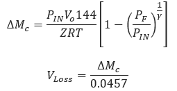
∆𝑀𝑐 − Mass Loss[lbs]
𝑉𝐿𝑜𝑠𝑠 − Gas Volume Lost[MSCF]
Input Parameters
- To create a new case, click the “Add Case” button
- Select the Gas Pipeline Blowdown – Semiempirical Model – Report No. 87-2 application from the Pipeline Testing module.
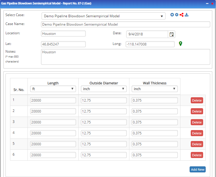
- Enter Case Name, Location, Date and any necessary notes.
- Fill out all required fields.
- Make sure the values you are inputting are in the correct units.
- Click the CALCULATE button.
- Pb – Base Pressure(psia)
- Pi – Initial Pressure(psig)
- Pf – Final Pressure(psig)
- Lo – Main Line Pipe Length(ft)
- do – Main Line Pipe Internal Diameter(in)
- L – Blowdown Pipe Length(ft)
- d – Internal Diameter of Blowdown(in)
- dr – Diameter at Choke Flow Point(in)

Outputs/Reports
- View the results.
- If an input parameter needs to be edited be sure to hit the CALCULATE button after the change.
- To SAVE, fill out all required case details then click the SAVE button.
- To rename an existing file, click the SAVE As button. Provide all case info then click SAVE.
- To generate a REPORT, click the REPORT button.
- The user may export the Case/Report by clicking the Export to Excel/PowerPoint icon.
- To delete a case, click the DELETE icon near the top of the widget.
