
Pull Force and Installation Stresses for PE Pipe
Pull Force and Installation Stresses – PE Pipe
The procedures for designing the bore path for plastic pipe are basically the same as discussed for steel pipe. As with steel product pipe, plastic pipe, when installed by HDD, may experience high-tension loads, severe bending, and external fluid pressures. HDD installation subjects the pipe to axial tensile forces caused by the frictional drag between the pipe and the bore hole or drilling fluid, the frictional dragon the ground surface, the capstan effect around drill-path bends, and hydrokinetic drag. The pipe may also be subjected to external hoop pressures caused by the external fluid head and bending stresses. Estimating of pullback forces involves the assumption of many variables and installation techniques.
Estimated Average Radius of Curvature at Pipe Entry and Pipe Exit:

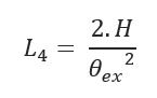
H – Depth of bore (ft)
Θin – Pipe entry angle (degree)
Θex – Pipe exit angle (degree)
L2 – Horizontal Distance to Achieve Desired Depth: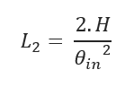
L4 – Horizontal Distance to Achieve Rise to the Surface:
L3 – Additional Distance Traversed at Desired Depth:
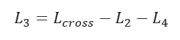
Lcross – Length of the Crossing
Weight of Empty Pipe:
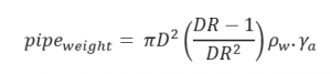
D – Pipe Diameter (inch)
DR – Pipe Dimension Ratio
γa – Specific Gravity of Pipe Material
Average Weight of Empty Pipe: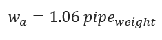
Water Weight:
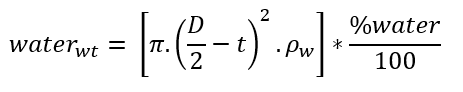
%water = Percentage of Pipe Filled with Water (percent)
ρw – Density of water (lb/ft3)
Net Upward Buoyant Force on Empty Pipe:
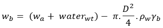
γb – Specific Gravity of the mud slurry
Hydrokinetic Force: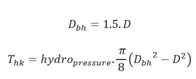
Pull Force at point A:
![]()
Pull Force at point B:![]()
Pull Force at point C:

Pull Force at point D:![]()
νa – Coefficient of Friction at the Surface
νb – Coefficient of Friction within Borehole
Bending Strain: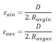
Bending Stress: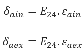
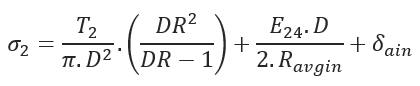
E24 = 24 hr.-Apparent Modulus of Elasticity
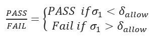
Allowable Tensile Stress: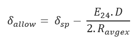
δsp – Allowable/Safe Pull Stress (psi)
Tensile Stress at Point A: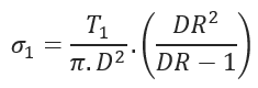
Tensile Stress at Point B:
Tensile Stress at Point C:
Tensile Stress at Point D: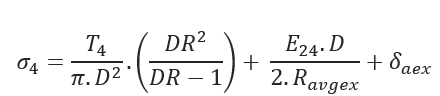
Breakaway Links Settings: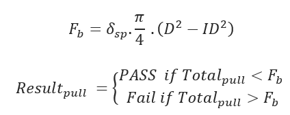
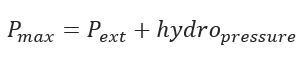
Static Head Pressure![]()
Maximum Pressure During Pull back
Ovality Compensation Factor: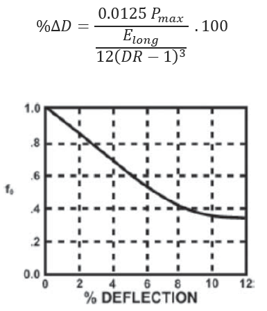
f0 – Ovality compensation factor based on % of Deflection (%Δ𝐷)
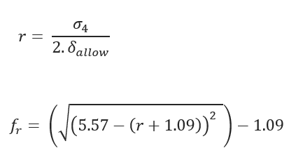
Tensile Reduction Factor:
Critical Collapse Pressure: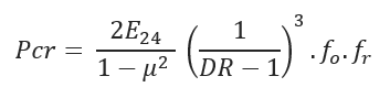
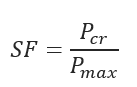
Safety Factor:
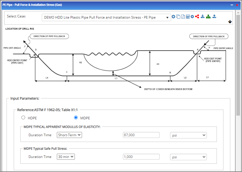
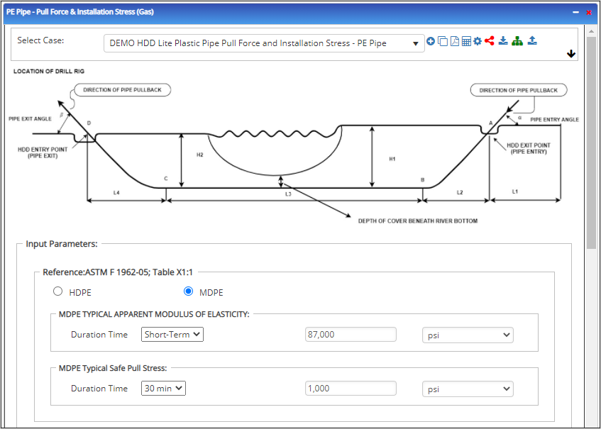
Input Parameters
- To create a new case, click the “Add Case” button
- Select the Pull Force and Installation Stresses – Vertical application in the HDD PE Pipe module.
- Enter Case Name, Location, Date and any necessary notes.
- Fill out all required fields.
- Make sure the values you are inputting are in the correct units.
- Click the CALCULATE button.
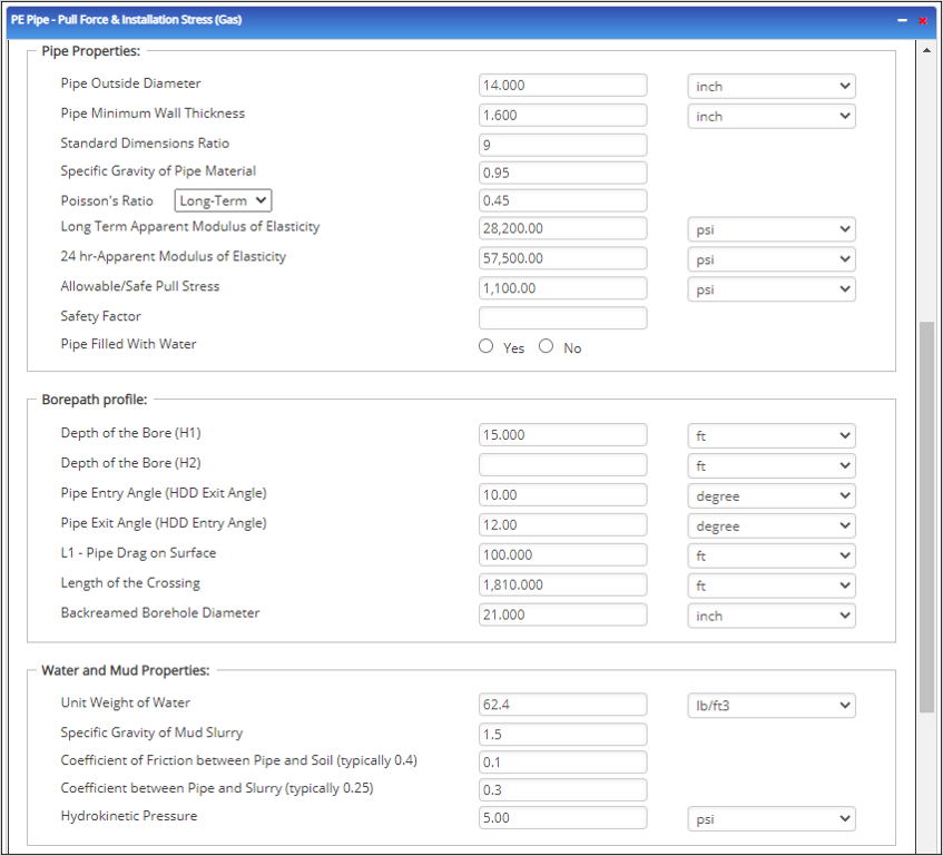
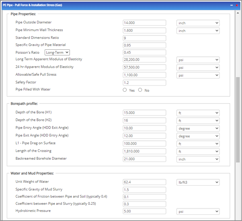
Pipe Properties:
- Pipe Outside Diameter (in) :(0.625” – 48”)
- Pipe Minimum Wall Thickness (in) :(0.068”- >2”)
- Standard Dimensions Ratio: Refer 49 CFR 192.121
- Specific Gravity of Pipe Material
- Poisson’s Ratio: (-1 – 0.5)
- Long Term Apparent Modulus of Elasticity (psi)
- 24 hr-Apparent Modulus of Elasticity (psi)
- Allowable/Safe Pull Stress (psi)
Borehole Path:
- Pipe Entry Angle (HDD Exit Angle) (degree)
- Pipe Exit Angle (HDD Entry Angle) (degree)
- L1 – Pipe Drag on Surface (ft)
- Length of the Crossing (ft)
- Backreamed Borehole Diameter (inch)
Water and Mud Properties:
- Unit Weight of Water (lb/ft3)
- Specific Gravity of Mud Slurry
- Coefficient of Friction between Pipe and Soil (typically 0.4)
- Hydrokinetic Pressure (psi)
Outputs/Reports
- View the results.
- If an input parameter needs to be edited be sure to hit the CALCULATE button after the change.
- To SAVE, fill out all required case details then click the SAVE button.
- To rename an existing file, click the SAVE As button. Provide all case info then click SAVE.
- To generate a REPORT, click the REPORT button.
- The user may export the Case/Report by clicking the Export to Excel/PowerPoint icon.
- To delete a case, click the DELETE icon near the top of the widget.
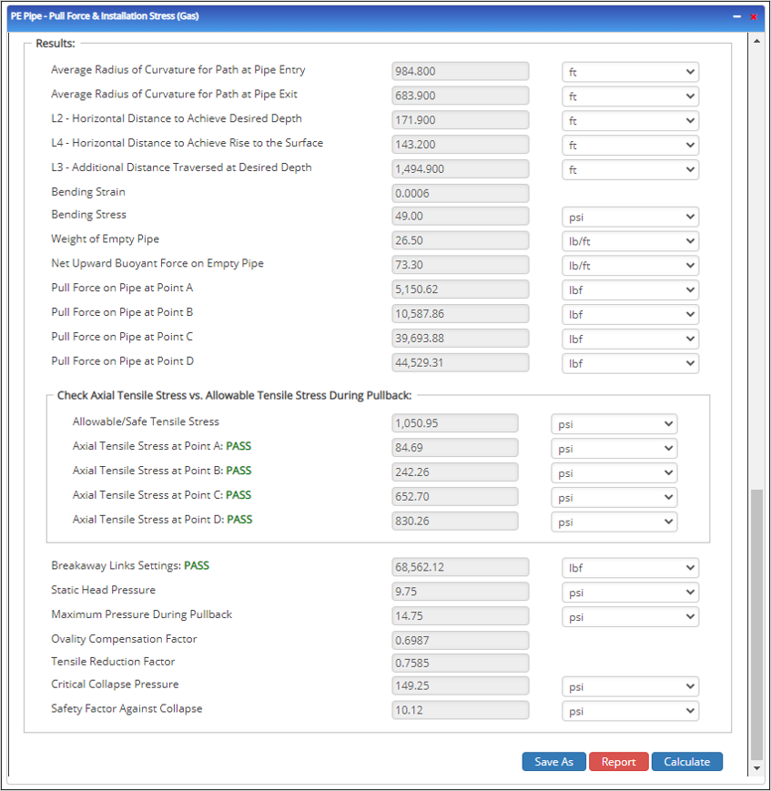
- Average radius of curvature for path at pipe entry (ft)
- Average radius of curvature for path at pipe exit (ft)
- L2 – Horizontal Distance to Achieve Desired Depth (ft)
- L4 – Horizontal Distance to Achieve Rise to the Surface (ft)
- L3 – Additional Distance Traversed at Desired Depth (ft)
- Bending Strain
- Bending Stress (psi)
- Weight of Empty Pipe (lb/ft)
- Net Upward Buoyant Force on Empty Pipe (lb/ft)
- Pull Force on Pipe at Point A (lb/ft)
- Pull Force on Pipe at Point B (lb/ft)
- Pull Force on Pipe at Point C (lb/ft)
- Pull Force on Pipe at Point D (lb/ft)
Check Axial Tensile Stress vs. Allowable Tensile Stress During Pullback:
- Allowable/Safe Tensile Stress (psi)
- Axial Tensile Stress at Point A (psi)
- Axial Tensile Stress at Point B (psi)
- Axial Tensile Stress at Point C (psi)
- Axial Tensile Stress at Point D (psi)
- Breakaway Links Settings (lbf)
- Static Head Pressure (psi)
- Maximum Pressure During Pullback (psi)
- Ovality Compensation Factor
- Tensile Reduction Factor
- Critical Collapse Pressure (psi)
- Safety Factor Against Collapse (psi)
Related Links
PLTB Gas and Liquid Services for Horizontal Direction Drilling Lite with Plastic Pipes
Table of Contents
Table of Pages
- Pipeline HUB User Resources
- AC Mitigation PowerTool
- API Inspectors Toolbox
- Horizontal Directional Drilling PowerTool
- Crossings Workflow
- Pipeline Toolbox
- Encroachment Manager
- PRCI AC Mitigation Toolbox
- PRCI Thermal Analysis for Hot-Tap Welding
- PRCI River-X
- PRCI RSTRENG
- RSTRENG+
- Ad-hoc Analysis
- Database Import
- Data Availability Dashboard
- ESRI Map
- Report Builder
- Hydrotest PowerTool
- Investigative Dig PowerTool
- Hydraulics PowerTool
- External Corrosion Direct Assessment Procedure - RSTRENG
- Canvas
- Definitions
- Pipe Schedule and Specifications Tables