
Pull Force and Installation Stresses – Vertical & Horizontal
Calculations
When pipes are installed by HDD, they often experience high tension loads, severe bending, and external fluid pressures. Often these installation loads are more severe than the design service loads. When selecting the appropriate pipe materials for an HDD installation, the designer must consider the pipe properties as well as the borehole profile. These two factors should be considered together in order to choose the best material and profile so that the pipeline can be installed and operated without risk of damage. To ensure that the material and bore-hole profile are suitable for the proposed application, the installation, operational, and combined loads and stresses are analyzed.
Pipe Weight in Air
𝑃𝑖𝑝𝑒𝑤𝑒𝑖𝑔ℎ𝑡 = 10.68(𝐷−𝑡)𝑡
𝑃𝑖𝑝𝑒𝑤𝑒𝑖𝑔ℎ𝑡– Weight of the pipe (lbs/ft)
D – Pipe Outside Diameter (inch)
t – Pipe Wall Thickness (inch)
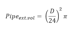
Pipe Exterior Volume
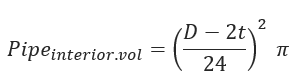
Pipe Interior Volume
Weight of Water in Pipe
(to be calculated only if the pipe is filled with water)
𝑊𝑎𝑡𝑒𝑟𝑃.𝑤𝑒𝑖𝑔ℎ𝑡 = 𝑃𝑖𝑝𝑒𝑖𝑛𝑡𝑒𝑟𝑖𝑜𝑟.𝑣𝑜𝑙 ∗ 𝑊𝑤𝑒𝑖𝑔ℎ𝑡
Displaced Mud Weight
𝐷𝑖𝑠𝑝𝑙𝑎𝑐𝑒𝑚𝑢𝑑𝑊𝑒𝑖𝑔ℎ𝑡 = 𝑃𝑖𝑝𝑒𝑒𝑥𝑡.𝑣𝑜𝑙𝑚𝑢𝑑𝑤𝑡
Effective Weight of Pipe
𝑊𝑆 = 𝑃𝑖𝑝𝑒𝑤𝑒𝑖𝑔ℎ𝑡 + 𝑊𝑎𝑡𝑒𝑟𝑃•𝑤𝑒𝑖𝑔ℎ𝑡 − 𝐷𝑖𝑠𝑝𝑙𝑎𝑐𝑒𝑚𝑢𝑑𝑊𝑒𝑖𝑔ℎ
Straight section A-B
Friction from Soil
𝑓𝑟𝑖𝑐2 = 𝑊𝑆𝐿1𝑐𝑜𝑠𝜃𝑆1𝜇𝑆𝑜𝑖𝑙
Drag Forces from Mud
𝐷𝑟𝑎𝑔2 = 𝜋𝐷𝐿1𝜇_𝑚𝑢
Tension on Section
∆𝑇2 = |𝑓𝑟𝑖𝑐2| + 𝐷𝑟𝑎𝑔2 − 𝑊𝑠𝐿1𝑠𝑖𝑛𝜃_𝑠1
Cumulative Pull Load
𝑇2 = ∆𝑇2 +𝑇1
Curved Section B-C
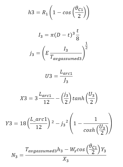
Friction from Soil
𝑓𝑟𝑖𝑐 = |𝑁3𝜇𝑆𝑜𝑖𝑙|
Drag Forces from Mud
𝐷𝑟𝑎𝑔3 = 𝜋𝐷𝐿𝑎𝑟𝑐1𝜇𝑚𝑢𝑑
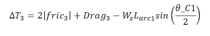
Tension on Section

Cumulative Pull Load
𝑇3 = ∆𝑇3 + 𝑇2
Straight Section C-D
Friction from Soil
𝑓𝑟𝑖𝑐4 = 𝑊𝑆𝐿𝑠𝑐𝑜𝑠𝜃𝑆𝜇𝑆𝑜𝑖𝑙
Drag Forces from Mud
𝐷𝑟𝑎𝑔4 = 𝜋𝐷𝐿𝑠𝜇𝑚𝑢𝑑
Tension on Section
∆𝑇4 = 𝑓𝑟𝑖𝑐4 + 𝐷𝑟𝑎𝑔4 − 𝑊𝑠𝐿𝑠𝑠𝑖𝑛𝜃𝑠
Cumulative Pull Load
𝑇2 = ∆𝑇4 + 3
Curved Section D-E
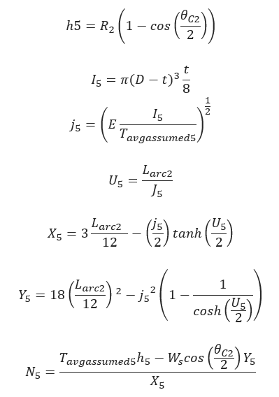
Friction from Soil
𝑓𝑟𝑖𝑐 = |𝑁3𝜇𝑆𝑜𝑖𝑙|
Drag Forces from Mud
𝐷𝑟𝑎𝑔3 = 𝜋𝐷𝐿𝑎𝑟𝑐1𝜇𝑚𝑢𝑑
Tension on Section
Cumulative Pull Load
𝑇3 = ∆𝑇3 + 𝑇2
Straight Section E-F
Friction from Soil
𝑓𝑟𝑖𝑐6 = 𝑊𝑆𝐿2𝑐𝑜𝑠𝜃𝑆2𝜇𝑆𝑜𝑖𝑙
Drag Forces from Mud
𝐷𝑟𝑎𝑔6 = 𝜋𝐷𝐿2𝜇𝑚𝑢𝑑
Tension on Section
∆𝑇6 = |𝑓𝑟𝑖𝑐6| + 𝐷𝑟𝑎𝑔6 + 𝑊𝑠𝐿1𝑠𝑖𝑛𝜃_𝑠1
Cumulative Pull Load
𝑇6 = ∆𝑇6 +𝑇5
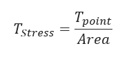
Tensile Stress at a Point
Allowable Tensile Stress
𝑇𝑆𝑡𝑟𝑒𝑠𝑠.𝑎𝑙𝑙𝑜𝑤 = 0.9𝑆𝑀𝑌𝑆
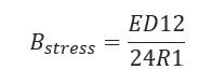
Bending Stress at a point
Allowable Bending Stress
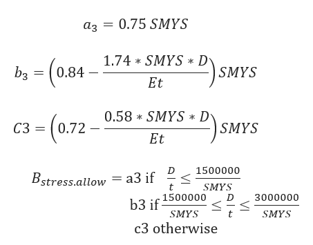
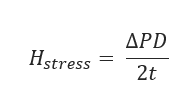
Hoop Stress at a point
Allowable Hoop Stress
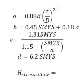
a. If 0.55𝑆𝑀𝑌𝑆 ≥ A
b. If 0.55 SMYS ≤ 𝑎 ≤ 1.6 𝑆𝑀𝑌𝑆
c. If 1.6 SMYS ≤ 𝑎 ≤ 6.2 𝑆𝑀𝑌𝑆
d. Otherwise
Unity Check – Tensile and Bending Stress
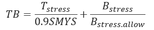
Unity Check – Tensile, Bending & Hoop Stress
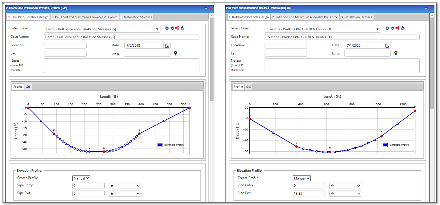
Input Parameters
- To create a new case, click the “Add Case” button
- Select the Pull Force and Installation Stresses – Vertical application in the HDD Steel Pipe module
- Enter Case Name, Location, Date, and any necessary notes
- Fill out all required fields
- Make sure the values you are inputting are in the correct units
- Click the CALCULATE button
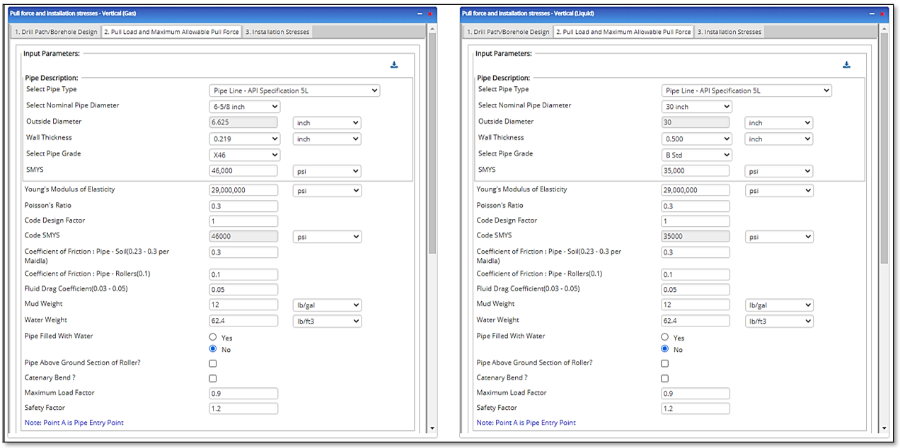
Pipe and Operational Characteristics:
- Nominal Pipe Size(in)
- Wall Thickness(in)
- Pipe Grade
- Pipe Outside Diameter(in)
- Pipe Entry Angle (°)
- SMYS – Specified Minimum Yield Strength(psi)
- Design Factor
- Young’s Modulus of Elasticity(psi)
- Poisson’s Ratio
- Coefficient of Friction: Pipe – Soil (0.21 – 0.3)
- Coefficient of Friction: Pipe – Rollers (0.1)
- Fluid Drag Coefficient (0.03 – 0.05) (psi)
- Mud Weight (lbs./ft³)
- Water Weight(lb./ft)
- Pipe Filled with Water:
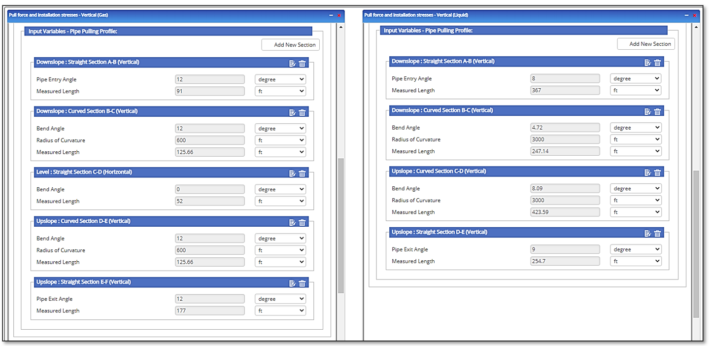
Installation and Site Characteristics:
- Measured Length: Section A-B
- Pipe Entry Angle (°)
- R1 – Radius of Curvature
- Measured Length: Section B-C
- Measured Length: Section C-D
- Pipe Exit Angle (°)
- R2- Radius of Curvature
- Measured Length: Section D-E
- Pipe Exit Angle (°)
- Measured Length: Section E-F
- Pipe Above Ground Section on Rollers
- Angle of Pipe Above Ground on Rollers
- Maximum Load Factor
- Safety Factor
Outputs/Reports
- View the results
- If an input parameter needs to be edited be sure to hit the CALCULATE button after the change
- To SAVE, fill out all required case details then click the SAVE button
- To rename an existing file, click the SAVE As button. Provide all case info then click SAVE
- To generate a REPORT, click the REPORT button
- The user may export the Case/Report by clicking the Export to Excel/PowerPoint icon
- To delete a case, click the DELETE icon near the top of the widget
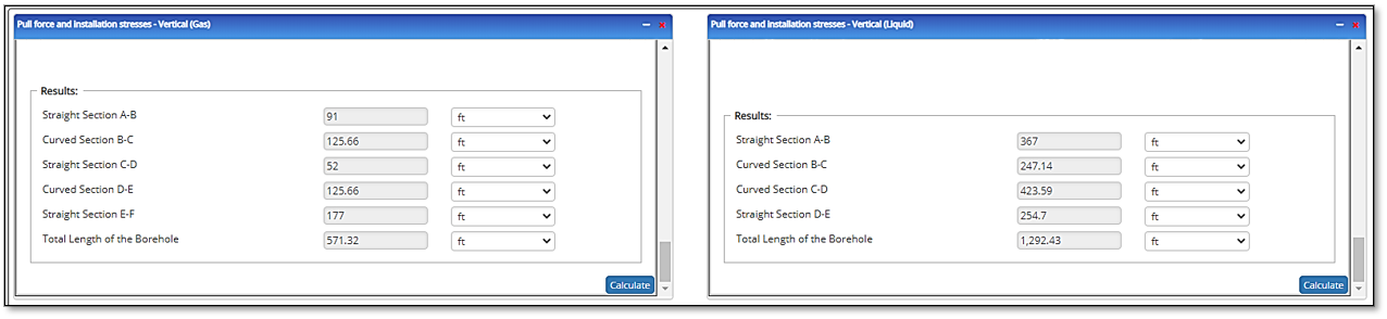
- Length of the Straight Section A-B
- Length of the Curved Section B-C
- Length of the Straight Bottom Section C-D
- Length of the Curved Section D-E
- Length of the Straight Section E-F
- Total Length of the Borehole
- Effective Submerged Weight (lb./ft)
- Pull Load Section on Rollers (lb.)
- Pull Load Straight Section 0-1 (lb.)
- Pull Load at Point 1 (lb.)
- Pull Load Curved Section 1-2 (lb.)
- Pull Load at Point 2 (lb.)
- Pull Load Straight Section 2-3 (lb.)
- Pull Load at Point 3 (lb.)
- Pull Load Curved Section 3-4 (lb.)
- Pull Load at Point 4 (lb.)
- Pull Load Straight Section 4-5 (lb.)
- Total Pull Load at Point 5 (lb.)
- Maximum Allowable Pull Force (lb.)
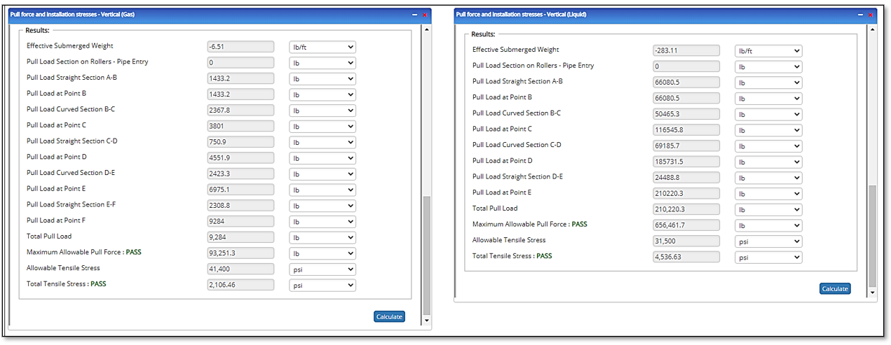
Pass/Fail:
- Allowable Tensile Stress (psi)
- Total Tensile Stress (psi)
Pass/Fail:
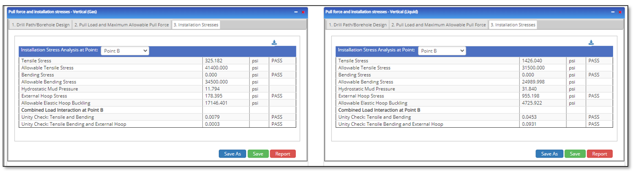
Select Point of Interest (B)
- Tensile Stress(psi)
- Allowable Tensile Stress(psi)
- Bending Stress(psi)
- Allowable Bending Stress(psi)
- Hydrostatic Mud Pressure(psi)
- External Hoop Stress(psi)
- Allowable Elastic Hoop Buckling
- Combined Load Interaction at Point
- Unity Check: Tensile and Bending
- Unity Check: Tensile, Bending, and External Hoop
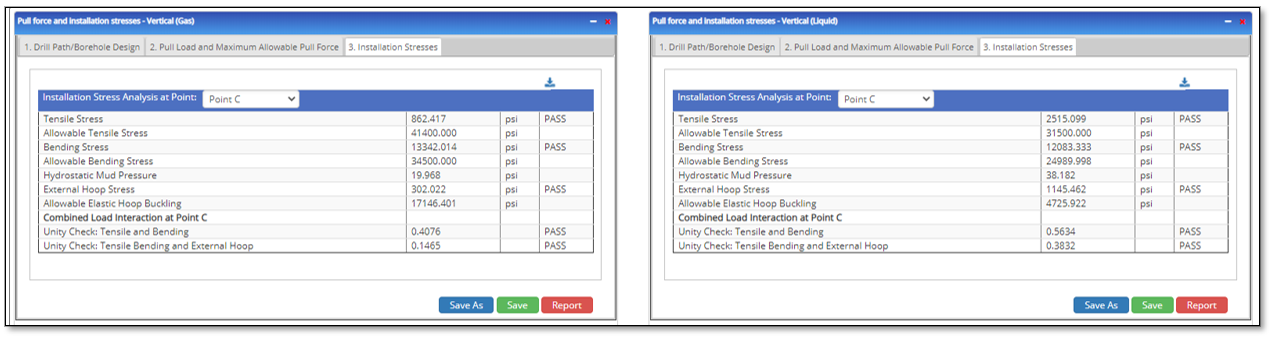
Select Point of Interest (C)
- Tensile Stress(psi)
- Allowable Tensile Stress(psi)
- Bending Stress(psi)
- Allowable Bending Stress(psi)
- Hydrostatic Mud Pressure(psi)
- External Hoop Stress(psi)
- Allowable Elastic Hoop Buckling
- Combined Load Interaction at Point
- Unity Check: Tensile and Bending
- Unity Check: Tensile, Bending, and External Hoop
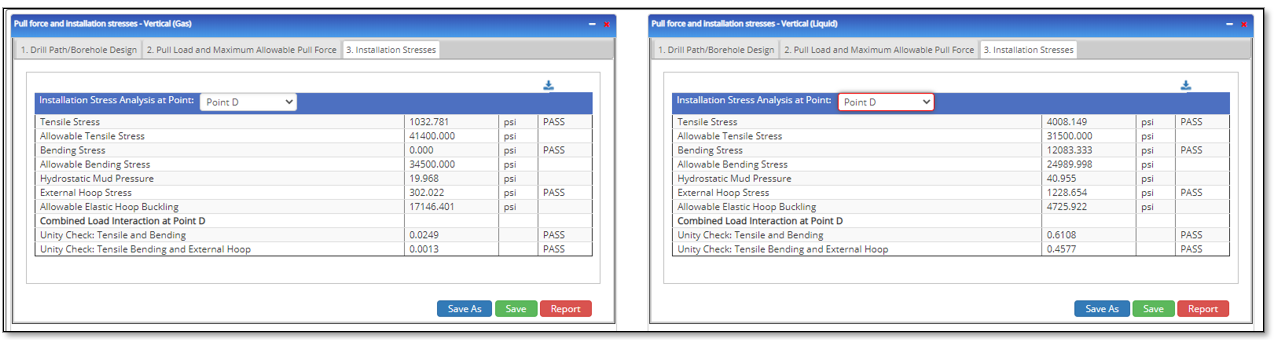
Select Point of Interest (D)
- Tensile Stress(psi)
- Allowable Tensile Stress(psi)
- Bending Stress(psi)
- Allowable Bending Stress(psi)
- Hydrostatic Mud Pressure(psi)
- External Hoop Stress(psi)
- Allowable Elastic Hoop Buckling
- Combined Load Interaction at Point
- Unity Check: Tensile and Bending
- Unity Check: Tensile, Bending, and External Hoop
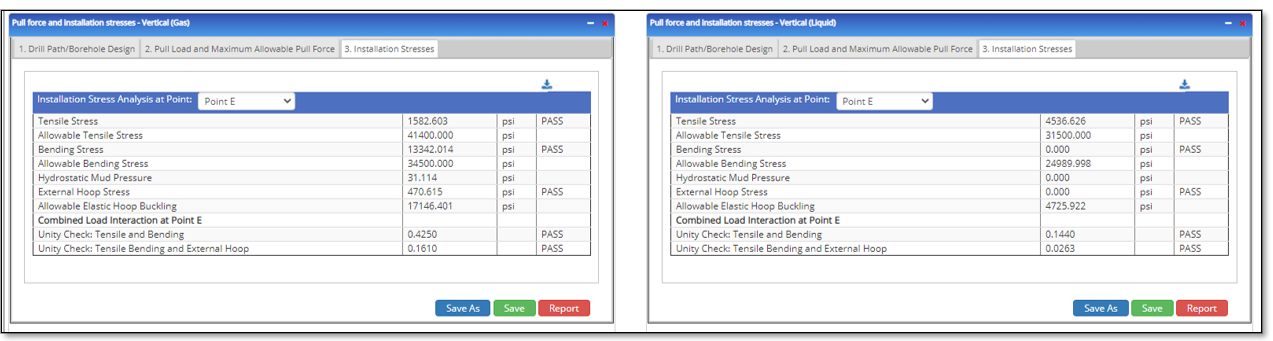
Select Point of Interest (E)
- Tensile Stress(psi)
- Allowable Tensile Stress(psi)
- Bending Stress(psi)
- Allowable Bending Stress(psi)
- Hydrostatic Mud Pressure(psi)
- External Hoop Stress(psi)
- Allowable Elastic Hoop Buckling
- Combined Load Interaction at Point
- Unity Check: Tensile and Bending
- Unity Check: Tensile, Bending, and External Hoop
Select Point of Interest (F)
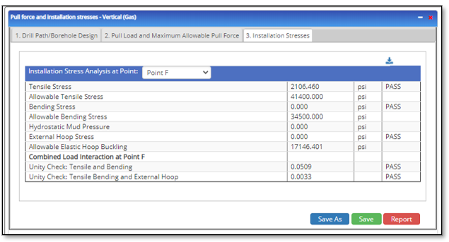 Tensile Stress(psi)
- Allowable Tensile Stress(psi)
- Bending Stress(psi)
- Allowable Bending Stress(psi)
- Hydrostatic Mud Pressure(psi)
- External Hoop Stress(psi)
- Allowable Elastic Hoop Buckling
- Combined Load Interaction at Point
- Unity Check: Tensile and Bending
- Unity Check: Tensile, Bending, and External Hoop
Related Links
Pipeline HUB — User ResourcesPLTB Gas & Liquid Services – Horizontal Direction Drill – Steel Pipes
Table of Contents
Table of Pages
Table of Contents
- Pipeline HUB User Resources
- AC Mitigation PowerTool
- API Inspector's Toolbox
- Horizontal Directional Drilling PowerTool
- Crossings Workflow
- Hydrotest PowerTool
- Pipeline Toolbox
- Encroachment Manager
- PRCI AC Mitigation Toolbox
- PRCI RSTRENG
- RSTRENG+
- Ad-hoc Analysis
- Database Import
- Data Availability Dashboard
- ESRI Map
- Report Builder
- Crossings Workflow
- Hydrotest PowerTool
- Investigative Dig PowerTool
- Hydraulics PowerTool
- External Corrosion Direct Assessment Procedure - RSTRENG
- Canvas
- Definitions
- Pipe Schedule and Specifications Tables