
IGT Distribution Equation
This equation is like the Panhandle and Weymouth equations even though slightly different constants are used. This equation, like others, was implemented to determine a pressure drop in a pipe segment under various flow rates. The IGT equation produces a large amount of error, decreasing with increasing flow rate and large changes in elevation. This indicates that the IGT Equation could be more accurate for higher flowrates and pressures of natural gas.
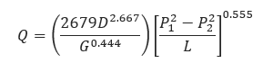
𝑄 − Flow Rate (FT3/day)
𝐷 − Internal Pipe Diameter (in)
𝐿 − Length of Pipeline(mi)
𝑃1 − Upstream Pressure (psi)
𝑃2 − Downstream Pressure (psi)
𝐺 − Gas Specific Gravity
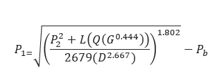
𝑄 − Flow Rate (FT3/day)
𝐷 − Internal Pipe Diameter (in)
𝐺 − Gas Specific Gravity
𝐿 − Length of Pipeline(mi)
𝑃1 − Upstream Pressure (psi)
𝑃2 − Downstream Pressure (psi)
𝑃𝑏 − Pressure Base (14.73 psi)
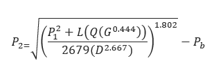
𝑄 − Flow Rate (FT3/day)
𝐷 − Internal Pipe Diameter (in)
𝐺 − Gas Specific Gravity
𝐿 − Length of Pipeline(mi)
𝑃1 − Upstream Pressure (psi)
𝑃2 − Downstream Pressure (psi)
𝑃𝑏 − Pressure Base (14.73 psi)
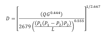
𝐷 − Internal Pipe Diameter (in)
𝑄 − Flow Rate (FT3/day)
𝐺 − Gas Specific Gravity
𝐿 − Length of Pipeline(mi)
𝑃1 − Upstream Pressure (psi)
𝑃2 − Downstream Pressure (psi)
Input Parameters
- To create a new case, click the “Add Case” button
- Select the Unknown and desired Flow Equation.
- Enter Case Name, Location, Date and any necessary notes.
- Fill out all required fields.
- Make sure the values you are inputting are in the correct units.
- Click the CALCULATE button.
- Temperature base(°F)
- Pressure base(psia)
- Gas Flowing Temperature(°F)
- Gas Specific Gravity
- Compressibility Factor
- Pipeline Efficiency Factor
- Upstream Pressure(psig)
- Flow Rate(MCFD)
- Internal Pipe Diameter(in)
- Length of Pipeline(mi)
- Upstream Elevation(ft)
- Downstream Elevation(ft)
Outputs/Reports
- View the results.
- If an input parameter needs to be edited be sure to hit the CALCULATE button after the change.
- To SAVE, fill out all required case details then click the SAVE button.
- To rename an existing file, click the SAVE As button. Provide all case info then click SAVE.
- To generate a REPORT, click the REPORT button.
- The user may export the Case/Report by clicking the Export to Excel/PowerPoint icon.
- To delete a case, click the DELETE icon near the top of the widget.
- Flow Rate(ft/sec.)
- Transmission Factor
- Velocity(ft/sec.)
- Upstream Pressure(psi)
- Transmission Factor
- Velocity(ft/sec.)
- Downstream Pressure(psi)
- Transmission Factor
- Velocity(ft/sec.)
- Internal Pipe Diameter(in)
- Transmission Factor
- Velocity(ft/sec.)
- Erosional Velocity
- Sonic Velocity
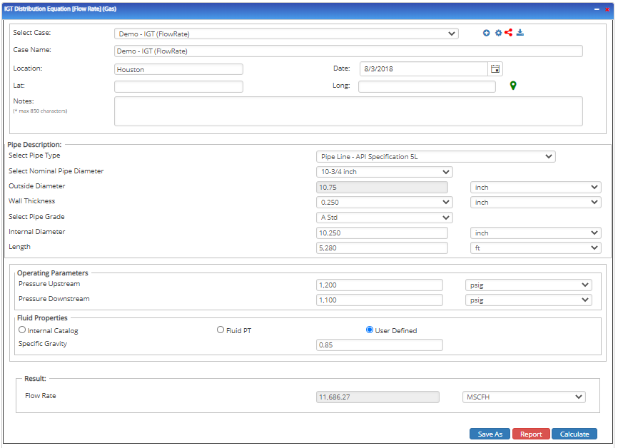
Flow Rate
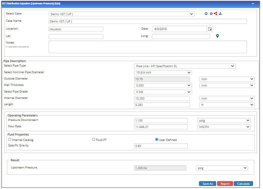
Upstream Pressure
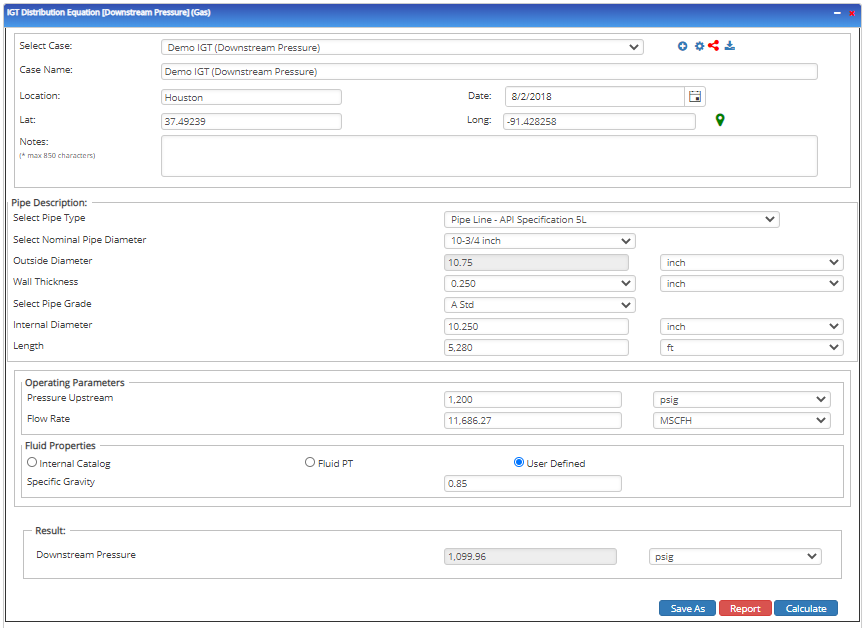
Downstream Pressure
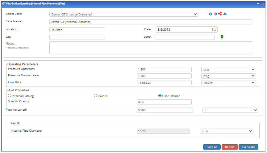
Internal Pipe Diameter
Related Links
Table of Contents
Table of Pages
Table of Contents
- Pipeline HUB User Resources
- AC Mitigation PowerTool
- API Inspector's Toolbox
- Horizontal Directional Drilling PowerTool
- Crossings Workflow
- Hydrotest PowerTool
- Pipeline Toolbox
- Encroachment Manager
- PRCI AC Mitigation Toolbox
- PRCI RSTRENG
- RSTRENG+
- Ad-hoc Analysis
- Database Import
- Data Availability Dashboard
- ESRI Map
- Report Builder
- Crossings Workflow
- Hydrotest PowerTool
- Investigative Dig PowerTool
- Hydraulics PowerTool
- External Corrosion Direct Assessment Procedure - RSTRENG
- Canvas
- Definitions
- Pipe Schedule and Specifications Tables