
Panhandle B
Panhandle B equation is used in the design of large high pressure, long transmission pipelines.
The Panhandle B equation is considered suitable for Reynolds numbers from:
𝑅𝑒 = 4𝑥106 𝑡𝑜 40𝑥116
The equation can be adjusted through the use of an efficiency term that makes it applicable across a relatively limited range of Reynolds numbers. Other than this, however, there are no means for adjustment of the equation to correct it for variations in pipe surface. Adjusted to an average flowing Reynolds number, the equation will predict low flow rates at low Reynolds numbers, and high flow rates at high Reynolds numbers, as compared to a fully turbulent flow equation. Efficiencies based on the Panhandle B equation decrease with increasing flow rate for fully turbulent flow. The efficiency factor, E, used in the Panhandle B equation generally varies between about 0.88 and 0.94.
These Panhandle A and B equations suffer from the substitution of a fixed gas viscosity value into the Reynolds number expression, which, in turn, substituted into the flow equation, results in an expression with a preconditioned bias.
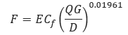
𝐹 − Transmission Factor
E – Pipeline Efficiency Factor
𝐶𝑓 − 16.7
𝑄 − Flow Rate (FT3/day)
𝐺 − Gas Specific Gravity
𝐷 − Internal Diameter (in)
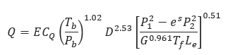
𝑄 − Flow Rate (FT3/day)
E – Pipeline Efficiency Factor
𝐶𝑄 − 737
𝑇𝑏 − Temperature Base (°R)
𝑃𝑏 − Pressure Base (psi)
𝐷 − Internal Diameter (in)
𝑃1 − Upstream Pressure (psi)
𝑃2 − Downstream Pressure (psi)
𝐺 − Gas Specific Gravity
𝐿𝑒 − Pipe Segment Length including Expansion (mi)
𝑇𝑓 − Gas Flowing Temperature(°R)
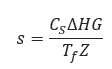
𝑠 − Elevation adjustment parameter
𝐶𝑆 − 0.0375
𝑍 − Compressibility Factor
𝑇𝑓 − Gas Flowing Temperature(°R)
∆𝐻𝐺 − Change in Elevation(ft)
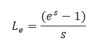
𝐿𝑒 − Pipe Segment Length including Expansion(mi)
𝑠 − Elevation adjustment parameter
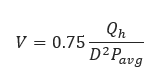
𝑉 − Velocity (ft/sec)
𝑄ℎ − Volumetric flow rate (scf/hr)
𝐷 − Internal Diameter (in)
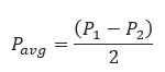
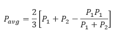
𝑃𝑎𝑣𝑔 − Average Pipeline Pressure (psia)
𝐅𝐨𝐫 𝐬𝐦𝐚𝐥𝐥 𝐩𝐫𝐞𝐬𝐬𝐮𝐫𝐞 𝐝𝐫𝐨𝐩 𝐏𝟐 >𝟎.𝟖 𝐏𝟏
𝐅𝐨𝐫 𝐥𝐚𝐫𝐠𝐞 𝐩𝐫𝐞𝐬𝐬𝐮𝐫𝐞 𝐝𝐫𝐨𝐩:
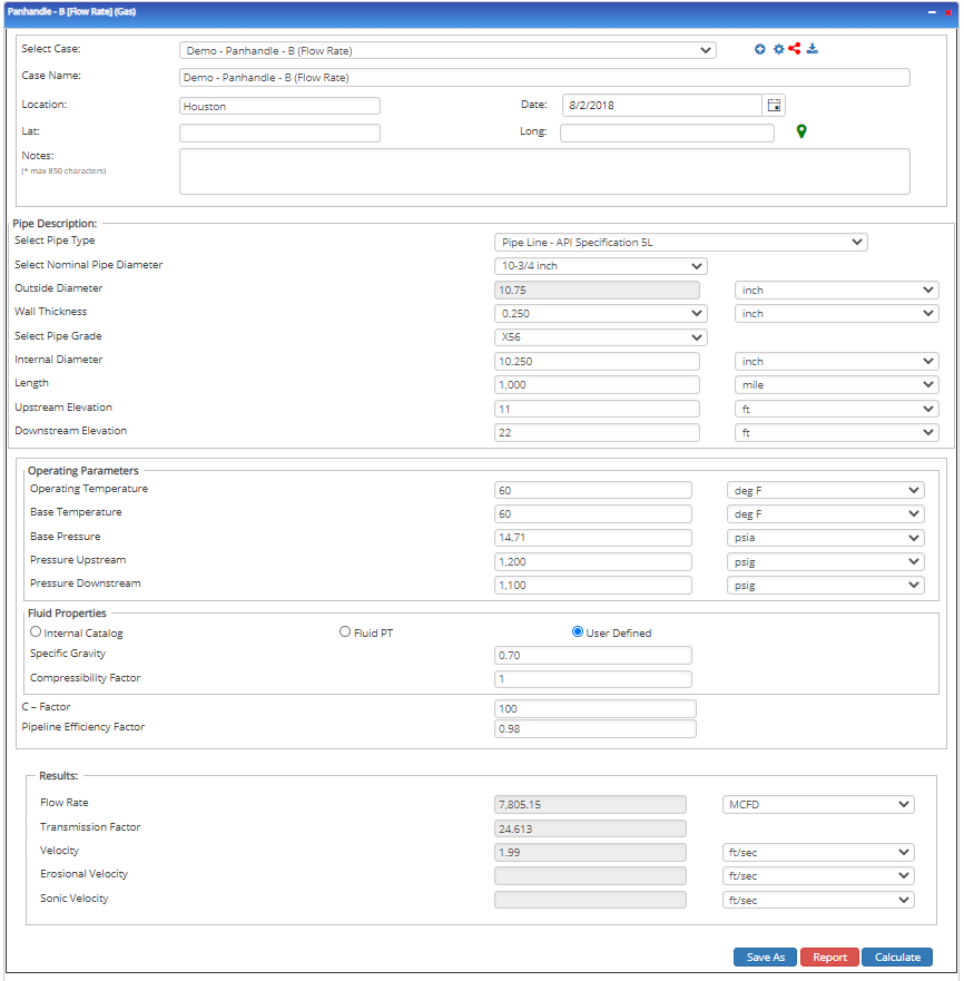
Input Parameters
- To create a new case, click the “Add Case” button
- Select the Unknown and desired Flow Equation
- Enter Case Name, Location, Date, and any necessary notes
- Fill out all required fields
- Make sure the values you are inputting are in the correct units
- Click the CALCULATE button
- Temperature base(°F)
- Pressure base(psia)
- Gas Flowing Temperature(°F)
- Gas Specific Gravity
- Compressibility Factor
- Pipeline Efficiency Factor
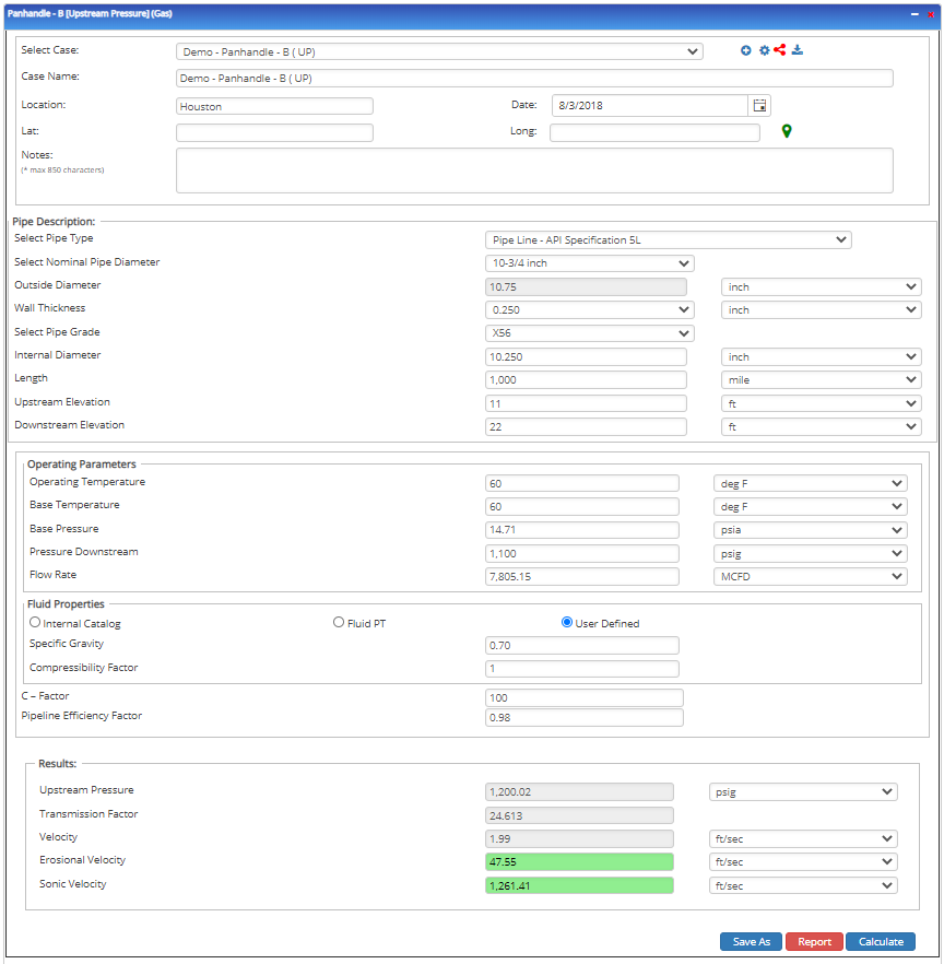
- Upstream Pressure(psig)
- Flow Rate(MCFD)
- Internal Pipe Diameter(in)
- Length of Pipeline(mi)
- Upstream Elevation(ft)
- Downstream Elevation(ft)
Outputs/Reports
- View the results
- If an input parameter needs to be edited be sure to hit the CALCULATE button after the change
- To SAVE, fill out all required case details then click the SAVE button
- To rename an existing file, click the SAVE As button. Provide all case info then click SAVE
- To generate a REPORT, click the REPORT button
- The user may export the Case/Report by clicking the Export to Excel/PowerPoint icon
- To delete a case, click the DELETE icon near the top of the widget
- Flow Rate(ft/sec.)
- Transmission Factor
- Velocity(ft/sec.)
- Upstream Pressure(psi)
- Transmission Factor
- Velocity(ft/sec.)
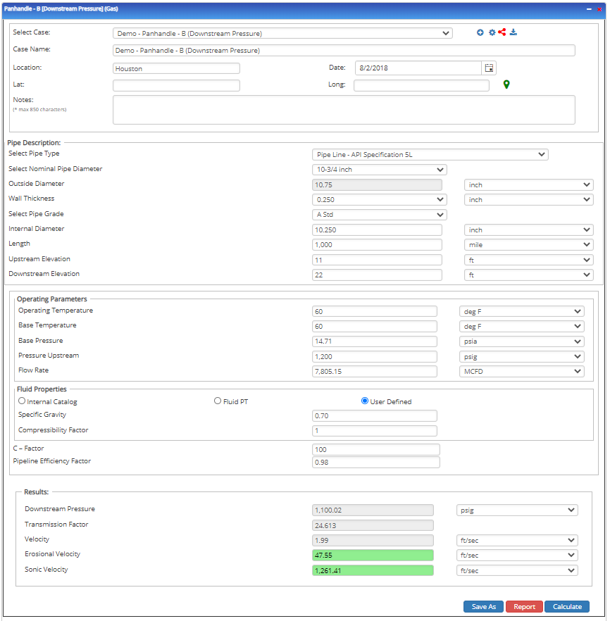
- Downstream Pressure(psi)
- Transmission Factor
- Velocity(ft/sec.)
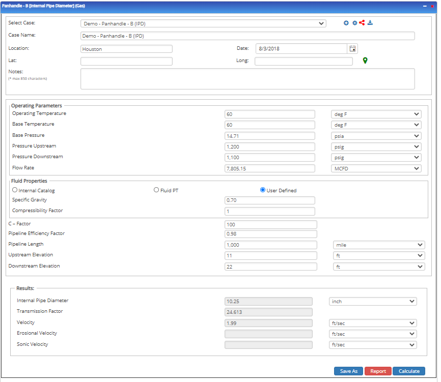
- Internal Pipe Diameter(in)
- Transmission Factor
- Velocity(ft/sec.)
- Erosional Velocity
- Sonic Velocity
Flow Rate
Upstream Pressure
Downstream Pressure
Internal Pipe Diameter
Related Links
Table of Contents
Table of Pages
Table of Contents
- Pipeline HUB User Resources
- AC Mitigation PowerTool
- API Inspector's Toolbox
- Horizontal Directional Drilling PowerTool
- Crossings Workflow
- Hydrotest PowerTool
- Pipeline Toolbox
- Encroachment Manager
- PRCI AC Mitigation Toolbox
- PRCI RSTRENG
- RSTRENG+
- Ad-hoc Analysis
- Database Import
- Data Availability Dashboard
- ESRI Map
- Report Builder
- Crossings Workflow
- Hydrotest PowerTool
- Investigative Dig PowerTool
- Hydraulics PowerTool
- External Corrosion Direct Assessment Procedure - RSTRENG
- Canvas
- Definitions
- Pipe Schedule and Specifications Tables