
Live Load: Distributed Surface Load on Buried PE Pipe – Unpaved Road Only
This calculation determines the deflection or structural damage to the repeated load application not over buried pipe i.e. parallel. However, it does not take into account concentrated heavy loading, inadequate cover, or unstable soils.
Dead/Earth Load
A. Prism Load
𝑃𝑝 = 𝑤𝐻
𝑃𝑝 = Vertical Soil Pressure,[lb/ft2]
𝑤 = Unit Weight of Soil,[lb/ft2]
𝐻 = Height of Soil Above Pipe Crown,[ft]
B. Marston Load (ASCE Manual No.60)
𝑃𝑚 = 𝐶𝑑𝑤𝐵𝑑
𝑃𝑚 = Vertical Soil Pressure,
[lb/ft2]
𝑤 = Unit Weight of Soil,
[lb/ft2]
𝐵𝑑 = Trench Width at Pipe Crown,[ft]
𝐶𝑑 = Load/Trench Coefficient
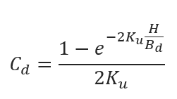
𝑒 = Base of Natural Logarithm,[2.71828]
𝐾 = Rankine Earth Pressure Coefficient
𝐾 = 𝑡𝑎𝑛2 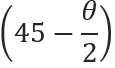
𝜃 = Angle of Internal Soil Friction, [°]
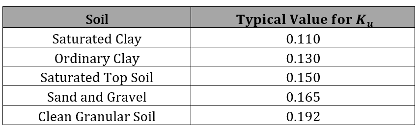
𝑢 = Coefficient of Friction between Backfill and Trench Sides
C. Combined Prism and Marston Load
For flexible pipe, a more conservative method is to use a soil pressure load in between prism and Marston load:
𝑃𝑐 = 0.6𝑃𝑚 + 0.4𝑃𝑝
𝑃𝑐 = Combined Load or Modified Arching Soil Pressure, [lb/ft2]
Live Load: Distributed Load on Buried PE Pipe – Unpaved Road Only
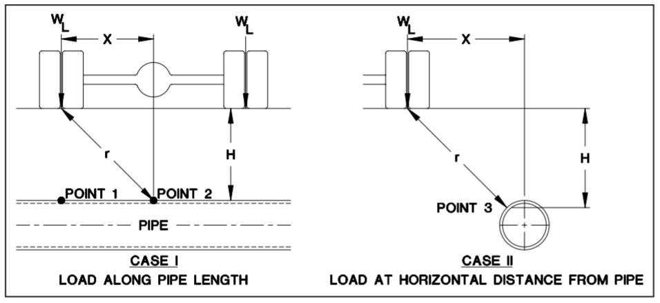
The Boussinesq Equation gives the pressure at any point in a soil mass under a concentrated surface load. The Boussinesq Equation may be used to find the pressure transmitted from a wheel load to a point that is not along the line of action of the load. Pavement effects are neglected.
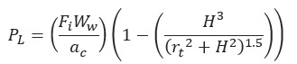
𝑃𝐿 = Vertical Soil Pressure due to Live Load [lb/ft2]
𝑊𝑤 = Live Load [lb/ft2] (see table)
𝐻 = Soil Height above Pipe Crown [ft]
𝐹𝑖 = Impact Factor
𝑎𝑐 = Contact Area [ft2]
𝑟𝑡 = Distance from the Point of Load Application [ft]
𝑟𝑡 = 
For standard H-20 and H-20 highway vehicle loading, the contact area is normally taken for dual wheels, that is, 16,000 lb. over a 10 in. by 20 in. area.
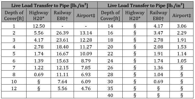
* Simulates a 20-ton truck traffic load, with impact factor
† Simulates an 80,000 lb./ft railway load, with impact factor
‡ Applies to 180,000 lb. dual-tandem gear assembly, with 26 in. spacing between tires and 66 in. center to center spacing between fore and aft tire under a rigid 12 in. pavement, with impact factor
§ Negligible influence of live load on buried pipe
Pipe Deflection is calculated using Spangler’s Modified Iowa Formula:
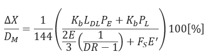
∆𝑋 = Horizontal Deflection[in]
𝐷𝑀 = Mean Diameter[in]
𝐾𝑏 = Bedding Factor
𝐿𝐷𝐿 = Deflection Lag Factor
𝑃𝐸 = Vertical Soil Pressure due to Earth Load[lb/ft2]
𝑃𝐿 = Vertical Soil Pressure due to Live Load]lb/ft2]
𝐸 = Apparent Modulus of Elasticity of Pipe Material[psi]
𝐸′ = Modulus of Soil Reaction[psi]
𝐹𝑆 = Soil Support Factor
𝐷𝑅 = Standard Dimension Ratio DR 
𝐷𝑜 = Pipe Outside Diameter [in]
𝑡 = Minimum Pipe Wall Thickness [in]
- Modulus of Soil Reaction (E’) – Average Values for Iowa Formula (see table in section 2.0)
- Modulus of Soil Reaction (E’) – Values of E’ for Pipe Embedment (see table in section 2.0)
- Values of E’n Native Soil Modules of Soil Reaction (see table in section 2.0)
- Soil Support Factor (see table in section 2.0)
Pipe Wall Compressive Stress
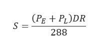
𝑆 = Pipe Wall Compressive Strength [psi]
𝑃𝐸 = Vertical Soil Pressure due to Earth Load[lb/ft2]
𝑃L = Vertical Soil Pressure due to Live Load [lb/ft2]
𝐷𝑅 = Standard Dimension Ratio DR 
𝐷𝑜 = Pipe Outside Diameter [in]
𝑡 = Minimum Pipe Wall Thickness [in]
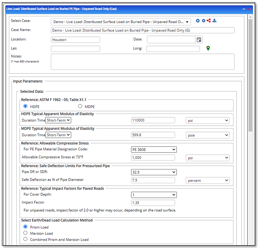
Input Parameters
- To create a new case, click the “Add Case” button
- Select the Live Load: Distributed Surface Load on Buried PE Pipe – Unpaved Road Only application from the Polyethylene Pipe – Design & Stress Analysis module list.
- Enter Case Name, Location, Date and any necessary notes.
- Fill out all required fields.
- Make sure the values you are inputting are in the correct units.
- Click the CALCULATE button.
- Reference: ASTM F 1962
- HDPE Typical Apparent Modulus of Elasticity
- Duration Time
- Reference: Allowable Compressive Strength
- For PE Pipe Material Designation Code:
- Reference: Safe Deflection Limits for Pressurized Pipe
- Pipe DR/SDR
- Reference: Typical Impact Factor for Paved Road
- Depth of Cover
- Select Earth/Dead Load Calculation Method
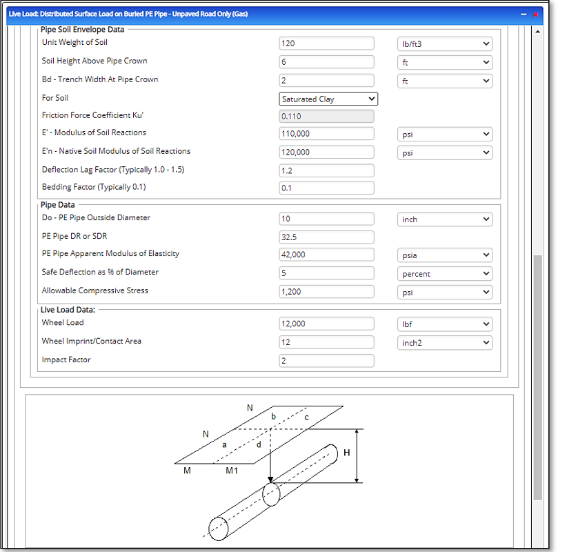
- Pipe Soil Envelope Data
- Unit Weight of Soil
- Soil Height above Pipe Crown
- Bd – Trench Width at Pipe Crown
- For Soil:
- Friction Force Coefficient Ku
- E’ – Modulus of Soil Reaction
- E’n- Native Soil Modulus of Soil Reaction
- Deflection Lag Factor (Typically 1.0 – 1.5)
- Bedding Factor (Typically 0.1)
- Pipe Data
- Do – PE Pipe Outside Diameter
- PE Pipe DR or SDR
- PE Pipe Apparent Modulus of Elasticity
- Safe Deflection as % of Diameter
- Allowable Compressive Stress
- Live Load
- Wheel Load
- L – Pipe Length
- Impact Factor
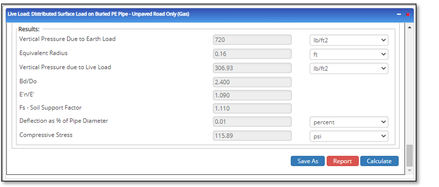
Outputs/Reports
- View the results.
- If an input parameter needs to be edited be sure to hit the CALCULATE button after the change.
- To SAVE, fill out all required case details then click the SAVE button.
- To rename an existing file, click the SAVE As button. Provide all case info then click SAVE.
- To generate a REPORT, click the REPORT button.
- The user may export the Case/Report by clicking the Export to Excel/PowerPoint icon.
- To delete a case, click the DELETE icon near the top of the widget.
- Vertical Pressure due to Earth Load
- Equivalent Radius
- Vertical Pressure due to Live Load
- Bd/Do
- E’n/E
- Fs – Soil Support Factor
- Deflection as % of Pipe Diameter
- Compressive Stress
Related Links
Table of Contents
Table of Pages
Table of Contents
- Pipeline HUB User Resources
- AC Mitigation PowerTool
- API Inspector's Toolbox
- Horizontal Directional Drilling PowerTool
- Crossings Workflow
- Hydrotest PowerTool
- Pipeline Toolbox
- Encroachment Manager
- PRCI AC Mitigation Toolbox
- PRCI RSTRENG
- RSTRENG+
- Ad-hoc Analysis
- Database Import
- Data Availability Dashboard
- ESRI Map
- Report Builder
- Crossings Workflow
- Hydrotest PowerTool
- Investigative Dig PowerTool
- Hydraulics PowerTool
- External Corrosion Direct Assessment Procedure - RSTRENG
- Canvas
- Definitions
- Pipe Schedule and Specifications Tables