Introduction
The River-X software is a popular tool and is widely used in the industry for integrity assessment of the exposed pipelines in river crossings. This software solution is the next generation of River-X tool which includes a robust user interface with several plotting and post-processing features. In addition, a new module for assessment of Girth weld with known defects using ECA methods has been developed.
Software Workflow
Introduction
This Guideline relates primarily to the situation where a pipeline originally buried for the full river channel crossing becomes exposed to the river flow. The exposure may be partial, and is not necessarily constant over the full width of the river channel.
The immediate concern is whether the actions of the river flow will lead to an unacceptable situation either due to movements, high stresses, or fatigue damage of the pipe.
Furthermore, the special conditions relative to the river and the pipeline crossing (floating debris, ice, ship traffic, scour, morphology, etc…) will need to be addressed toe stablish whether remedial actions are required.
The sequence of activities described is to be considered guidance only. Specific projects may have requirements which impose a different line of action.

Sequence of Activities
Basic Data and Information include data describing:
- Pipeline dimensions and structural properties
- Pipeline crossing conditions
- River discharge
- River bed conditions and soil properties
Pipeline data and operational parameters are normally associated with relatively little uncertainty, whereas data relating to the river conditions will display significant variations. The river discharge shows large seasonal variations and it is the maximum discharge for the period considered, which is of main interest.
Determination of the maximum river discharge requires, in general, a statistical analysis of a large amount of measured data or extensive hydrological modeling.
The immediate source of data and information is the original design documents. However, more recent information may be obtained either from authorities, the water board management, or may be collected through dedicated site investigations.
Design Conditions and Parameters include all data and information which are used directly in the calculations. The information is either given directly by the basic data or may be established using the basic data.
The pipeline dimensions, structural properties, and operational data are used to calculate load, stiffness, and resistance parameters.
Together with the river channel data, the discharge data is used to calculate the flow velocity, and information on the bed conditions is used to establish the boundary layer.
The data describing the river channel and the soil, together with the pipe structural data, define the pipeline support conditions and the end constraints.
Other basic data may provide information on possible impact loads, loads from ice, and other conditions which need to be considered.
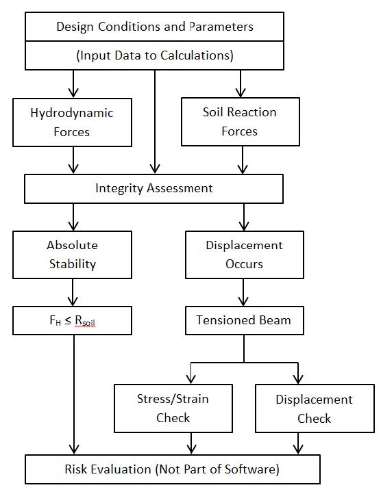
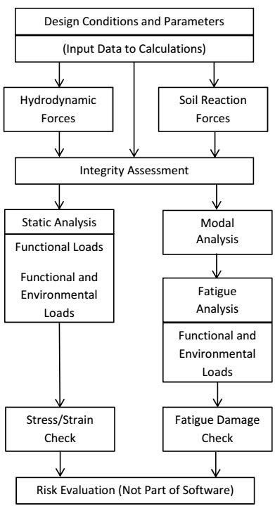
Integrity Assessment includes four main activities which relate directly to the actions of the river flow on the pipeline, namely:
- Lateral stability
- Free span evaluation
- Impact evaluation
- Engineering Critical Assessment (ECA)
The Guideline addresses primarily these four aspects which are described further in the following sections. Impact from floating debris or other objects transported by the river flow is treated in an approximative manner. The associated software deals with lateral stability, free span evaluation, impact evaluation and ECA.
A number of additional calculations and evaluations may be required dependent on the specific crossing. This can be:
- Scour consideration
- Ship traffic or third-party activities
- Ice loads
These subjects and maybe other relevant considerations are not included in the Theory Manual.
Risk assessments should include a probabilistic analysis. The Theory Manual specifies acceptance criteria for each individual analysis and givers some guidance on how the acceptance criteria may be used to evaluate the probability of failure, but any specific information on probabilistic analysis is not included.
In general, the river flow velocity is associated with the largest natural variability. The river channel geometry may of course also change due to erosion and sedimentation, but such changes are in most cases relatively moderate. A risk evaluation will therefore, in many cases, be performed by evaluating the probability of exceeding a certain flow velocity.
Lateral Stability
Lateral stability may either be absolute, or lateral movements of the pipeline may occur until the build-up of axial tension generates sufficient additional stabilization force.
Absolute stability exists when the maximum horizontal hydrodynamic force acting on the pipeline under the given flow conditions is smaller than the available horizontal soil reaction force.
In case the maximum soil reaction force is insufficient for stabilizing the pipeline, lateral movements occur, and because the pipeline is anchored in the river embankment, axial tension will build up, generating a supplementary stabilization force. The lateral movement required for developing the additional stabilization force depends on the dimensions of the pipeline.

Free Span Evaluation
According to the load definitions in the Theory Manual, the assessment of free spans includes three main calculations:
- Static analysis for functional loads alone (vertical loads)
- Static analysis for functional loads and simultaneous quasi-static environmental loads (vertical and horizontal loads)
- Fatigue analysis for functional loads and simultaneous dynamic environmental loads (vertical and horizontal loads including vortex shedding).

Impact Evaluation
Impact loads may be generated by floating debris or by boulders and stones transported along the river bed by the flow.
The impact loads may be estimated on the basis of the impulse loads. However, a number of simplifications of basic assumptions must be made in order to arrive at estimates of the impact force without having to perform extensive and complex modeling.
The basic assumptions that may be used to give an upper value for the maximum impact loads are:
- The impact is fully non-elastic
- The full kinetic energy of the transported object must be absorbed by deformation of the exposed pipeline section
ECA
With the development of structural steel to be stronger, more ductile, and to contain more fracture resistant capacity, modern pipelines are designed for harsher and harsher conditions with structural utilization pushed to be very close to 1, i.e. maximum stress is close to yield stress. In many cases, when a pipeline experiences large strain during installation (such as in reeling condition) or during operation (lateral buckling or seismic condition), the nominal longitudinal strain may go up to the order of 1% or 2%. as a result, modern pipeline design philosophy typically follows limit states comprising of Serviceability Limit State (SLS); Accidental Limit State (ALS); Fracture Limit State (FLS) and so on. Among them, the FLS may be performed through the Engineering Critical Assessment (ECA) for circumferential weld flaws in pipeline girth welds using fracture mechanics principles.
Generally, ECA may be applied in different phases of a pipeline project, from design to operation. In the design phase, ECA is typically used to determine maximum tensile capacity of the pipeline, which may be used as an alternative for the conventional acceptance criteria at yield stress level. In the installation phase, ECA is used to determine tolerable flaw sizes for pipeline girth welds, which will be then used to develop acceptance criteria for the welding. In operation, ECA is used, in fitness for service context, to assess the criticality of a known flaw detected in the girth welds.
The River-X ECA module is developed to perform the ECA for pipeline girth welds using Failure Assessment Diagram approach. As aforementioned, this module can be used in different phases of a pipeline project from design to operation.
Software Functionality and Architecture
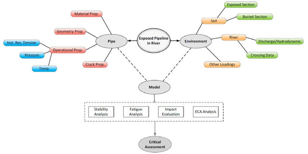
The new River-X software will perform various analyses on the exposed pipelines including Stability and Fatigue Analyses, Impact Evaluation, and Assessment of defects in the girth Welds. The required input data would depend on the selected analysis; however, those can be divided into a number of groups visualized in the following diagram:

