
Introduction
In this approach the active earth force is calculated due to simultaneous effect of both the soil weight and the surcharge of strip load over the pipe to determine earth pressures.
Dead/Earth Load
A. Prism Load
P_p=wH
P_p=wH
𝑃𝑝 = Vertical Soil Pressure, [lb/ft2]
𝑤 = Unit Weight of Soil, [lb/,ft2]
𝐻 = Height of Soil Above Pipe Crown, [ft]
B. Marston Load (ASCE Manual No.60)
P_m=C_dwB_d
P_m=C_dwB_d
𝑃𝑚 = Vertical Soil Pressure, [lb/,ft2]
𝑤 = Unit Weight of Soil, [lb/,ft2]
𝐵𝑑 = Trench Width at Pipe Crown, [ft]
𝐶𝑑 = Load/Trench Coefficient
C_d = \frac{1 – e^{-2K_u\frac{H}{B_d}}}{2K_u}
C_d = \frac{1 - e^{-2K_u\frac{H}{B_d}}}{2K_u}𝑒 = Base of Natural Logarithm, [2.71828]
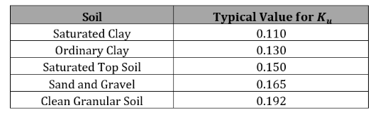
𝐾 = Rankine Earth Pressure Coefficient
𝐾 = 𝑡𝑎𝑛2 (45-θ/2)
𝜃 = Angle of Internal Soil Friction, [°]
𝑢 = Coefficient of Friction between Backfill and Trench Sides
C. Combined Prism and Marston Load
For flexible pipe, a more conservative method is to use a soil pressure load in between prism and Marston load:
𝑃𝑐 = 0.6𝑃𝑚 + 0.4𝑃𝑝
𝑃𝑐 = Combined Load or Modified Arching Soil Pressure, [lb/ft2]
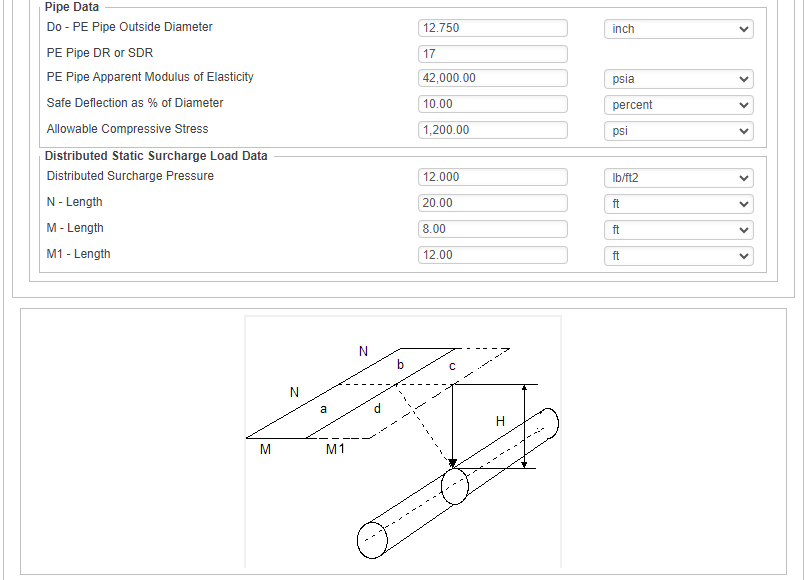
Distributed Static Surcharge Load Not Over PE Pipe
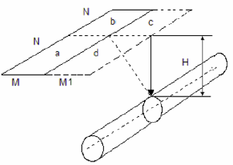
This method is using Boussinesq equation for pressure acting on pipe crown.
P_{dp} = P_{a+d} + P_{b+c} – P_c – P_d \
P_i = I_CW_i
P_{dp} = P_{a+d} + P_{b+c} - P_c - P_d \\
P_i = I_CW_i𝑃𝑑𝑝 = Subcharge Distributed Load Pressure at Point on Pipe Crown [lb/ft2]
𝑃𝑎+𝑑 = Combined Sub Area a and d Subcharge Load [lb/ft2]
𝑃𝑏+𝑐 = Combined Sub Area b and d Subcharge Load [lb/ft2]
𝑃𝑐 = Sub Area c Subcharge Load [lb/ft2]
𝑃𝑑 = Sub Area d Subcharge Load [lb/ft2]
𝑃𝑖 = Sub Area Subcharge Load at with Area[a+d,b+c,c or d]
𝐼𝐶 = Influence Coefficient
𝑤𝑖 = Distributed Surcharge Pressure Acting over with Area [a+b,b+c,c or d]
Influence coefficient is selected from the table below:
𝐻 = Vertical Distance from Surface to Crown of Pipe,[ft]
𝑀 = Horizontal Distance Normal to Pipe Centerline, from the Center of Load Area,[ft]
𝑁 = Horizontal Distance Parallel to Pipe Centerline, from the Center of Load Area,[ft]

Pipe Deflection is calculated using Spangler’s Modified Iowa Formula:
\frac{\Delta X}{D_M} = \frac{1}{144} \left( \frac{K_bL_{DL}P_E + K_bP_L}{\frac{2E}{3}(\frac{1}{DR-1} )+F_SE’} \right) \times 100\%
\frac{\Delta X}{D_M} = \frac{1}{144} \left( \frac{K_bL_{DL}P_E + K_bP_L}{\frac{2E}{3}(\frac{1}{DR-1} )+F_SE'} \right) \times 100\%
∆𝑋 = Horizontal Deflection,in.
𝐷𝑀 = Mean Diameter,in.
𝐾𝑏 = Bedding Factor
𝐿𝐷𝐿 = Deflection Lag Factor
𝑃𝐸 = Vertical Soil Pressure due to Earth Load[lb/ft2]
𝑃𝐿 = Vertical Soil Pressure due to Live Load[lb/ft2]
𝐸 = Apparent Modulus of Elasticity of Pipe Material[psi]
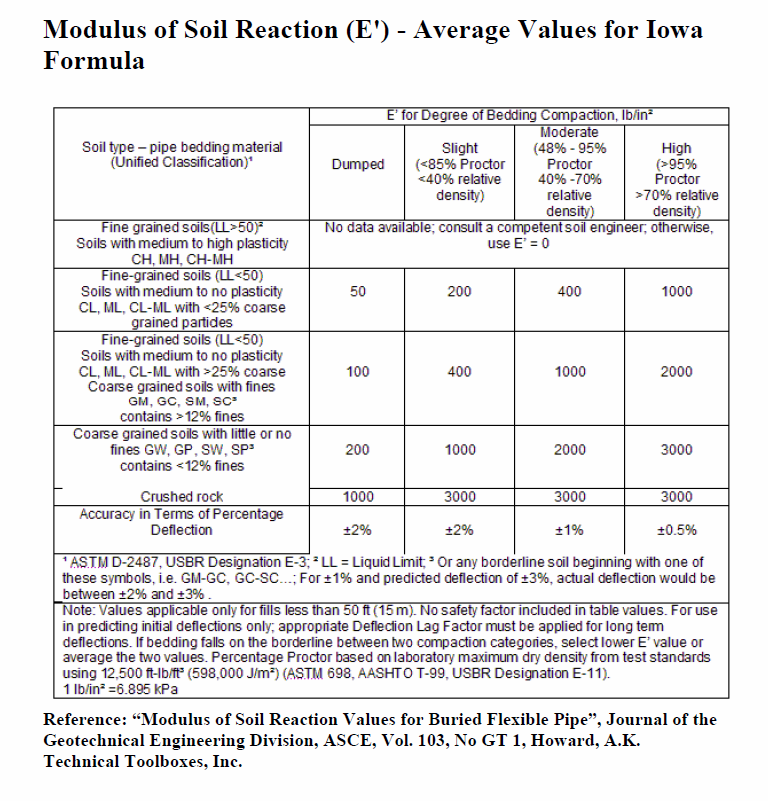
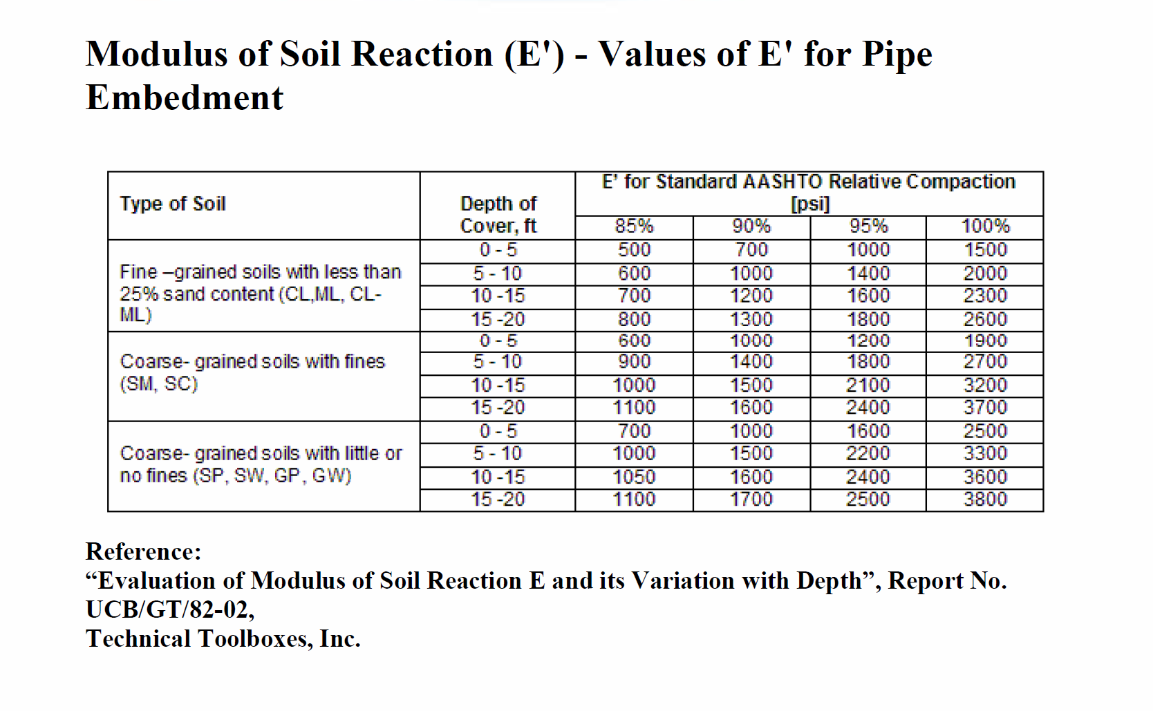
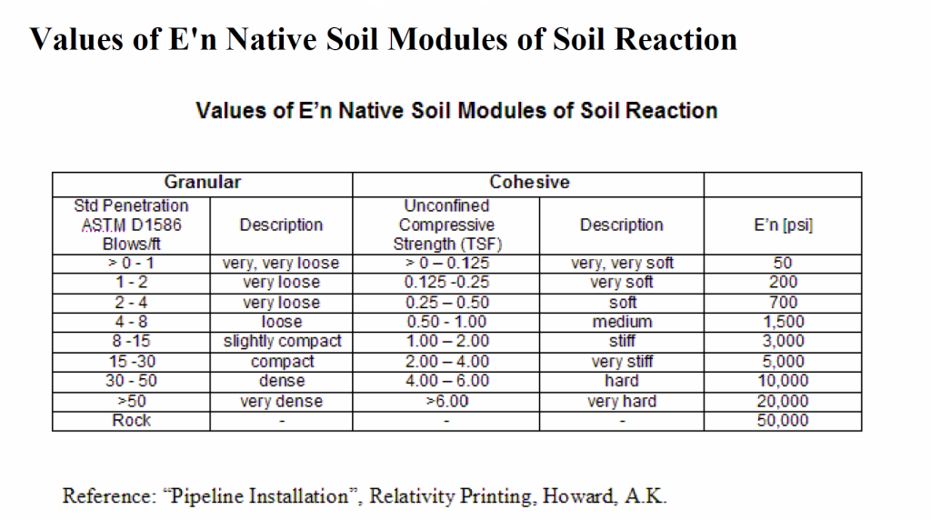
𝐸′ = Modulus of Soil Reaction[psi]
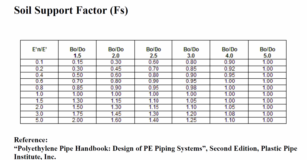
𝐹𝑆 = Soil Support Factor
𝐷𝑅 = Standard Dimension Ratio DR = Do /t
𝐷𝑜 = Pipe Outside Diameter [in]
𝑡 = Minimum Pipe Wall Thickness [in]
Parameter Reference Table:
Modulus of Soil Reaction (E’) – Average Values for Iowa Formula
Modulus of Soil Reaction (E’) – Values of E’ for Pipe Embedment
Values of E’n Native Soil Modules of Soil Reaction
Soil Support Factor (Fs)
Pipe Wall Compressive Stress (PE Pipe Crushing):
S=\frac{(P_E+P_S)DR}{288}
S=\frac{(P_E+P_S)DR}{288}𝑆 = Pipe Wall Compressive Strength [psi]
𝑃𝐸 = Vertical Soil Pressure due to Earth Load,[lb/ft2]
𝑃𝑆 = Vertical Soil Pressure due to Surcharge Load[lb/ft2]
𝐷𝑅 = Standard Dimension Ratio DR = Do /t
𝐷𝑜 = Pipe Outside Diameter [in]
𝑡 = Minimum Pipe Wall Thickness [in]
Case Guide
Part 1: Create Case
- Select the Distributed Static Surcharge Load: PE Pipe Not Directly Beneath a Surcharge Load application from the Polyethylene Pipe Module
- To create a new case, click the “Add Case” button
- Enter Case Name, Location, Date and any necessary notes.
- Fill out all required parameters.
- Make sure the values you are inputting are in the correct units.
- Click the CALCULATE button to overview results.
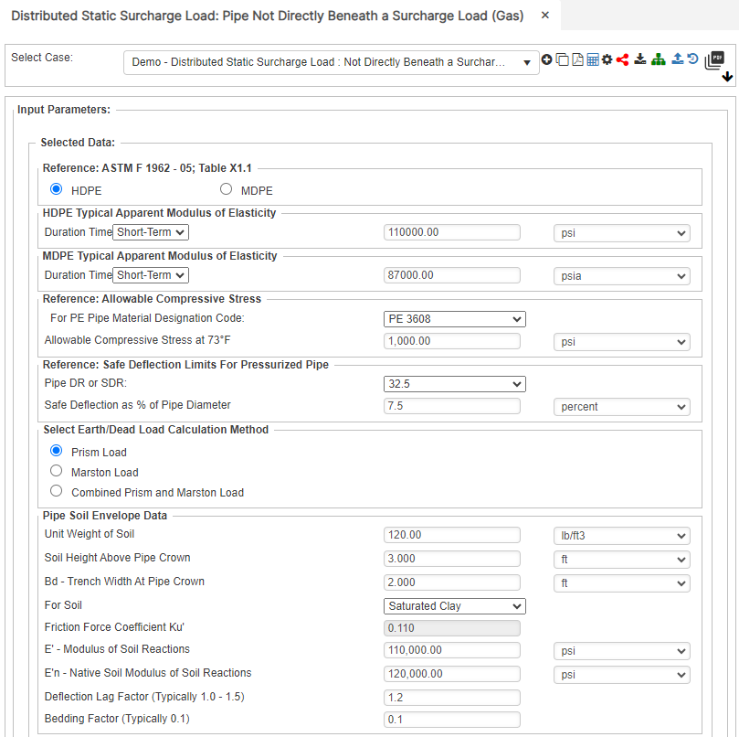
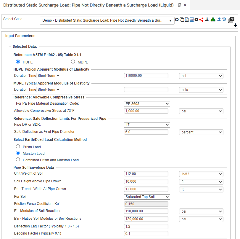
Input Parameters
- Reference: ASTM F 1962
- HDPE Typical Apparent Modulus of Elasticity
- Duration Time
- Reference: Allowable Compressive Strength
- For PE Pipe Material Designation Code:
- Reference: Safe Deflection Limits for Pressurized Pipe
- Pipe DR/SDR
- Select Earth/Dead Load Calculation Method
- Pipe Soil Envelope Data
- Unit Weight of Soil
- Soil Height above Pipe Crown
- Bd – Trench Width at Pipe Crown
- For Soil:
- Friction Force Coefficient Ku
- E’ – Modulus of Soil Reaction
- E’n- Native Soil Modulus of Soil Reaction
- Deflection Lag Factor (Typically 1.0 – 1.5)
- Bedding Factor (Typically 0.1)
- Pipe Data
- Do – PE Pipe Outside Diameter
- PE Pipe DR or SDR
- PE Pipe Apparent Modulus of Elasticity
- Safe Deflection as % of Diameter
- Allowable Compressive Stress
- Static Load
- Distributed Surcharge Pressure
- N – Length
- M – Length
- M1 – Length
Part 2: Outputs/Reports
- If you need to modify an input parameter, click the CALCULATE button after the change.
- To SAVE, fill out all required case details then click the SAVE button.
- To rename an existing file, click the SAVE As button. Provide all case info then click SAVE.
- To generate a REPORT, click the REPORT button.
- The user may export the Case/Report by clicking the Export to Excel icon.
- To delete a case, click the DELETE icon near the top of the widget.
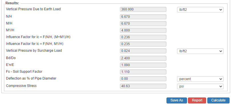
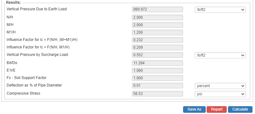
Results
- Vertical Pressure due to Earth Load (lb/ft2)
- N/H
- M/H
- M1/H
- Influence Factor for Ic = F (N/H, M/H)
- Influence Factor for Ic = F (N/H, M1/H)
- Vertical Pressure by Surcharge Load (lb/ft2)
- Bd/Do
- E’n/E
- Fs – Soil Support Factor
- Deflection as % of Pipe Diameter
- Compressive Stress (psi)
References
- “Modulus of Soil Reaction Values for Buried Flexible Pipe”, Journal of the Geotechnical Engineering Division, ASCE, Vol. 103, No GT 1, Howard, A.K. Technical Toolboxes, Inc.
- “Evaluation of Modulus of Soil Reaction E and its Variation with Depth”, Report No. UCB/GT/82-02,
- “Soil Engineering”, Third Edition, Spangler, M.G. and Handy, R.L., Intext Educational Press
- “Structural Mechanics of Buried Pipes”, Watkins, R.K, and Loren, R, A,
- “Polyethylene Pipe Handbook: Design of PE Piping Systems”, Second Edition, Plastic Pipe Institute, Inc.
- API 15LE – Specification for Polyethylene Line Pipe
FAQ
-
Properties of Polyethylene Pipes?
This property data is a summary of similar materials in the MatWeb database for the category “High Density Polyethylene (HDPE), Injection Molded”.
Each property range of values reported is minimum and maximum values of appropriate MatWeb entries. The comments report the average value, and number of data points used to calculate the average.
The values are not necessarily typical of any specific grade, especially less common values and those that can be most affected by additives or processing methods. Check Out