Barnes layer data are set up to represent the bulk soil multiple layers for the corrosive layer (pipe depth), deep layer (steady state and inductive fault) and conductive layer (conductive fault). Other considerations include:
- Where soil resistivity layers are not deep and change i.e., from deep tower footing grounds compared to the shallower pipeline trench, faults may stress the coating.
- Where these conditions exist, running multiple scenarios at the fault tower(s) are needed for to assess for various depths.
- Example, using the Barnes Layers in areas where there are deep HDD crossings is recommended. Adjustment to the spreadsheet calculations may be needed to accommodate these depths for more accurate assessment of these layers.
- In HDD crossings, it should be noted that drilling muds contain bentonite clays that have very low resistivities in the range of 100 ohm-cm. The soil resistivity meters may, or in most cases may not detect this narrow layer of the drilling muds around the pipe.
- If the backfill are typical soils, the drilling muds will migrate into the soil after several years.
- If the backfill is in granite or similar rock, the muds may remain in place for many years.
See attached as an example Excel Spreadsheet to setup multiple layers at the end of this manual.
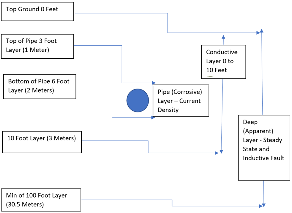
Deep (Apparent) Resistivity Layer should always be the deepest. It is recommended to get the most accurate results is to use a minimum of a 100-foot depth or 30.5 meters. It is used to assess Inductive Faults and Steady State inductive voltages. However, it has been reported that many users have used the common CP type soil resistivity meter readings with the calibrated 5’ intervals wiring that is limited to 20’ that matches the 20’ deep ground rods on towers.
Pipe (Barnes Resistivity) Layer should always be around the depth of the pipeline. Typical depths run from 3 to 6 feet or 1 to 2 meters except for HDD crossings. It is also used to calculate the current density of amps/m2.
Conductive Resistivity Layer should always be the top surface layer. Typical depths run from 3 to 10 feet or 1 to 3 meters. It used to calculate conductive faults, step/touch potentials and surface potentials or ground potential rise.
Example of Barnes Multi-Layers Soil Resistivity for AC Modeling and Mitigation: