
The question comes up from time to time how to address local stresses for wheel and track load calculations. ASME B31.8 833.9 Local Stresses states that the maximum allowable sum of circumferential stress due to internal pressure (Barlow Design Formula) and circumferential through-wall bending stress caused by surface vehicle loads or other local loads is 0.9ST, where S is the specified minimum yield strength, psi (MPA) per para. 841.1 (a), and T is the temperature derating factor per para. 841.1.8. In addition, repetitive loads may require further limitations in consideration for fatigue especially in hazardous liquid pipelines. It should be noted that the Code does not fully address the maximum value for all local stresses, and it is up to the engineer to determine these stresses.
A table was created by Battelle Research and large pipeline operator to do an analysis methodology for calculation of stresses in pipeline caused by encroachments or vehicle crossings. The theoretical work was done by M. G. Spangler on overburden and vehicle loads on pipelines, Battelle for vehicle loads and the pipeline operator did the verifications. This research has been the basis of what is used today in these programs.
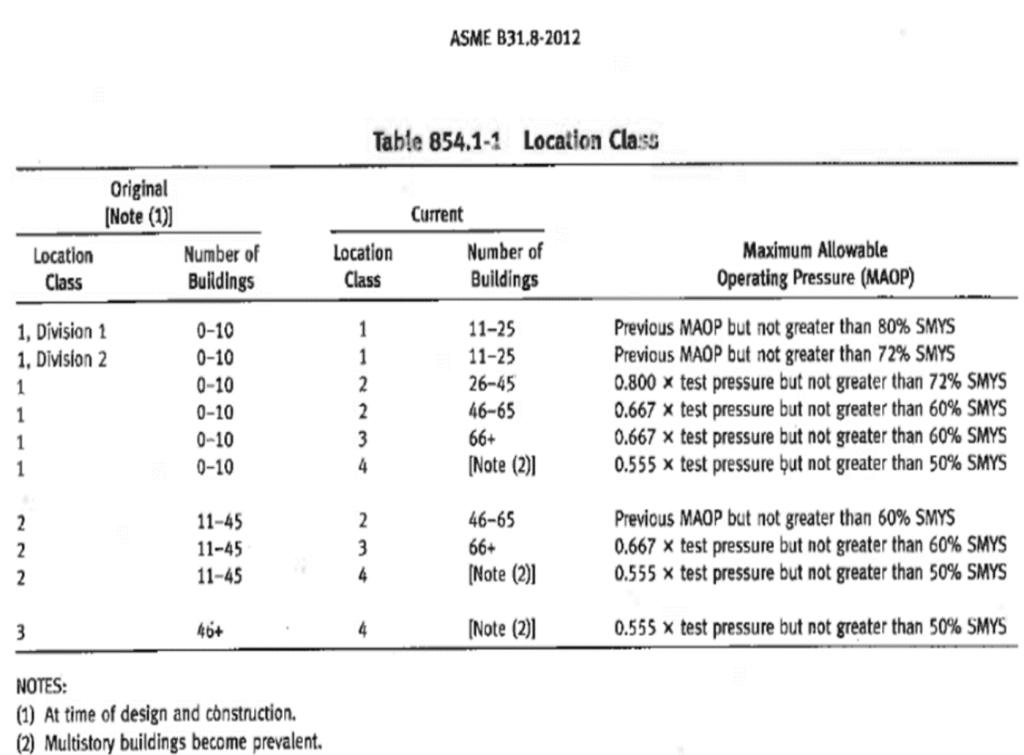
Below is a table from ASME for class locations:
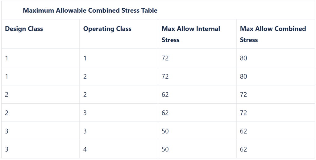
The pipeline operator’s specification in this research project was used in the following road crossing procedure to determine the maximum allowable stress (strain gages) for a particular design class location.
This research study was to develop a meaningful approach for evaluating the stresses at crossings. In addition, to these calculations, the beneficial effects of pavement (asphalt and concrete) and timber mats were included so that all the factors influencing the pipe stresses were considered.