
Overview
The Crossings Workflow was designed to simplify crossing analyses involving multiple pipe segments, multiple pieces of equipment with the various analysis tools used in crossing evaluations within the HUBPL application. Both multiple equipment/type of analysis and pipes are entered once, and the workflow tool performs the analyses across all combinations of pipe and equipment. Additionally, the Crossings Workflow may also be used to link, modify and edit crossing cases previously saved and run on a single pipe and equipment/type of analysis in the HUBPL Application.
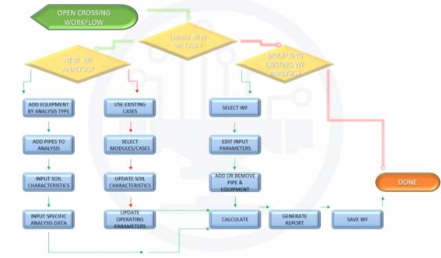
Workflow (New Analysis)
- Open Workflow – Pipeline Crossing from the blue ribbon.
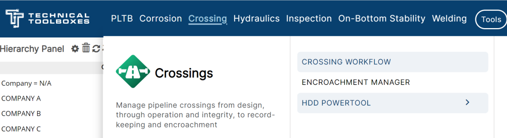
- Opens the Workflow Pipeline Crossing widget with the default case.
- To create a new case, click on Case and select Create New Case icon and select pipe category.
- Steel Pipe
- Polyethylene Pipe
- Enter a case name.
- Check on Collaborative if the user wants to share the case with other users from the same organization/company.
- Enter a location name.
- Date defaults to the current date upon a new case. The user can change to any desired date.
- User can either enter lat/long manually or use the green icon (beside the lat/long field) to drop a point in the map which populates the lat/long in the application.
- User can enter notes for a maximum of 850 characters.
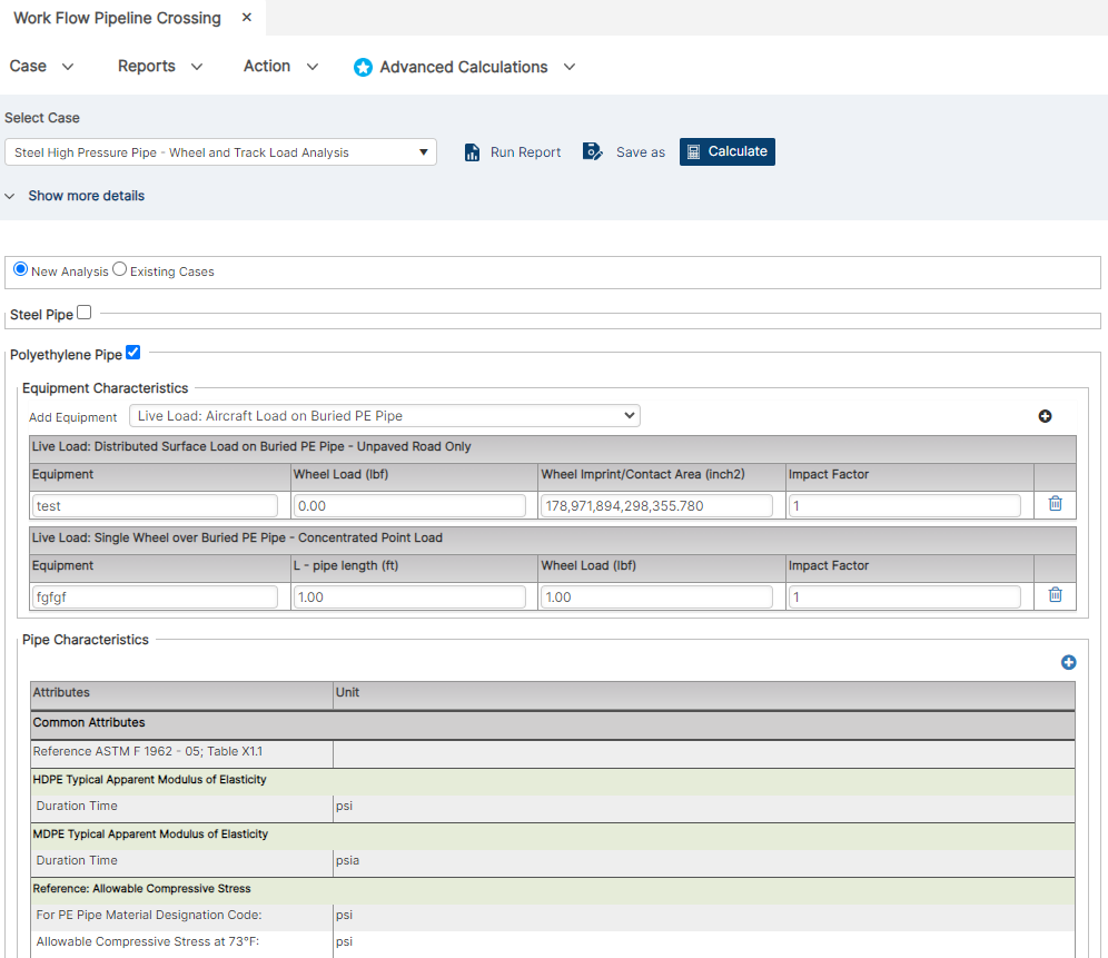
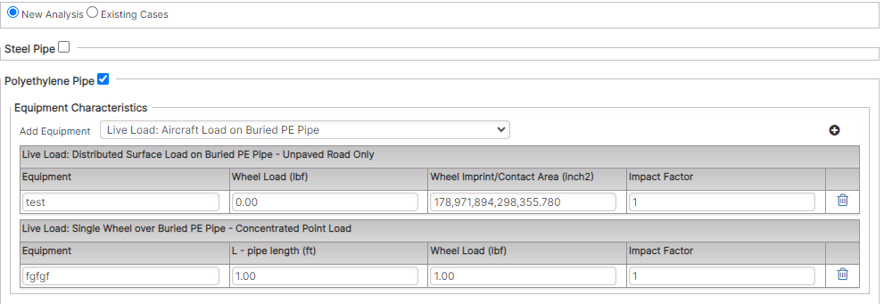
- The radio button option for “New Analysis” allows the user to create new workflow cases while “Existing Case” allows the user to use existing cases from PLTB Crossings module in the workflow application.
- For a new analysis, select the Equipment Characteristics (Steel Pipe or Polyethylene Pipe)
- Select the available equipment from the drop-down and click on the “Add Equipment” icon (blue plus icon) in the equipment characteristics section (there are no restrictions on the number of equipment items added).
- New Analysis – Steel Pipe
- New Analysis – Polyethylene Pipe
- User will enter the equipment-specific data for the calculations to be executed.
- Click on the “Add Pipe” (blue plus icon) in the pipe characteristics section.
- Adds new columns of pipes for every “Add Pipe” click (there are no restrictions in the number of pipes added).
- Add new pipe – Steel Pipe
- Add new pipe – Polyethylene Pipe

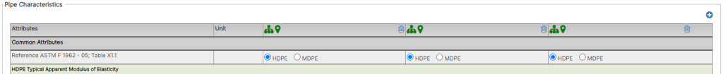
- The green branch icon allows the user to “Select pipe from hierarchy or map”. Click on the green branch icon and then select the pipe from the map/hierarchy. Displays the pipe name if available beside these icons.
- The green location icon allows the user to “Select pipe from map”. Click on the green location icon which launches the map where the user can drop a point on the pipe which populates the pipe data of the selected pipe along with the name, latitude, and longitude.
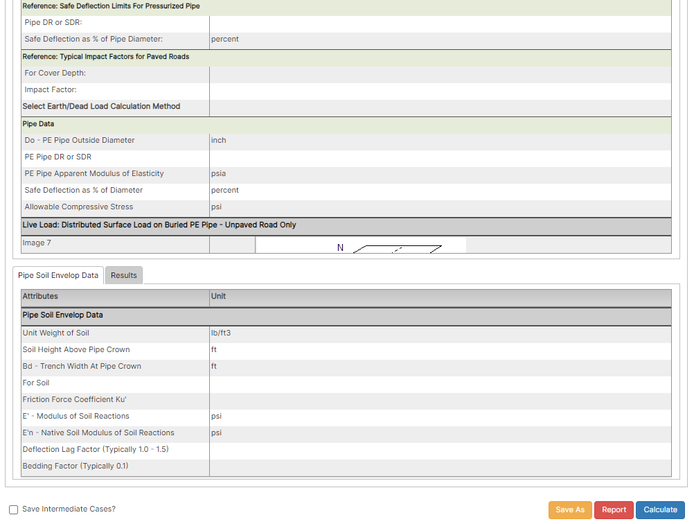
- User will have to enter all pipe variables separated into the selected equipment for the calculations to be executed.
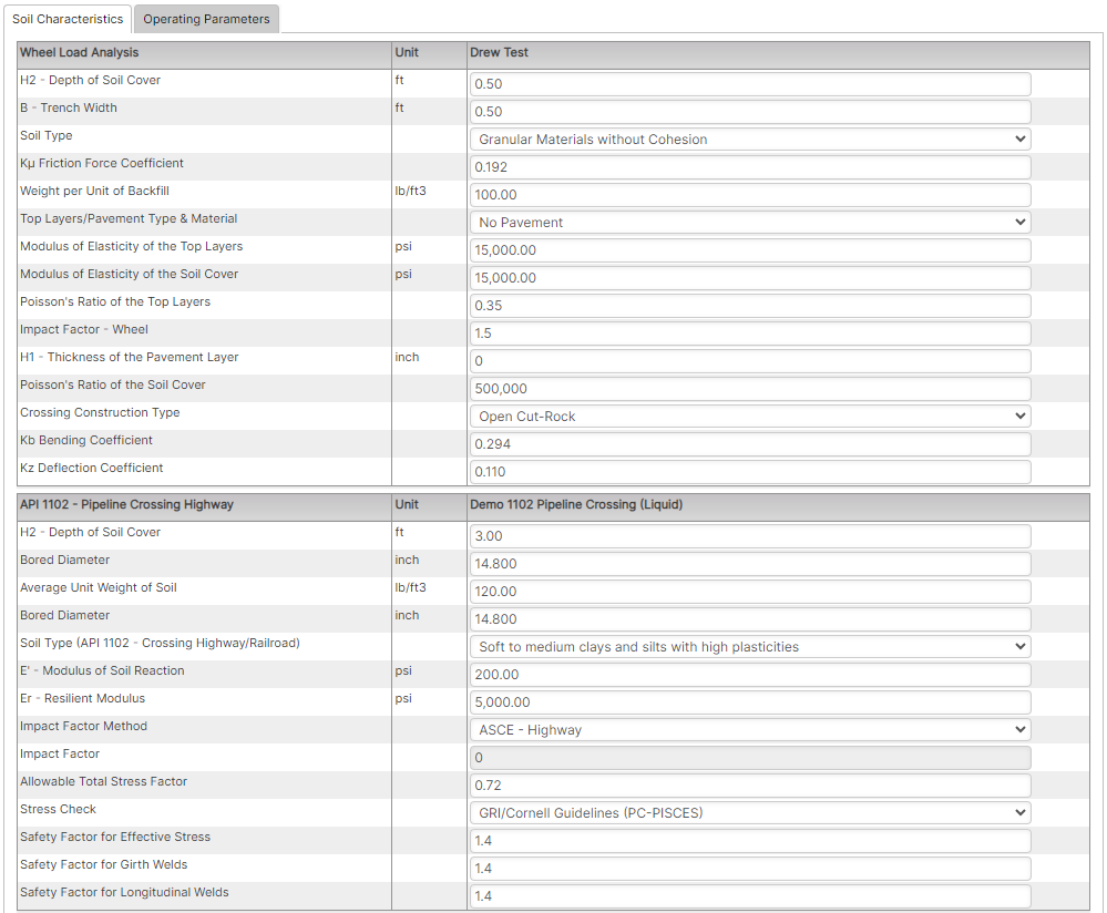
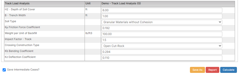
- User will have to enter the “Soil Characteristics” data for all added pipes which have been segregated based on the equipment selected/added by the user for the analysis.
- Soil Characteristics – Steel Pipe
- Soil Characteristics – Polyethylene Pipe
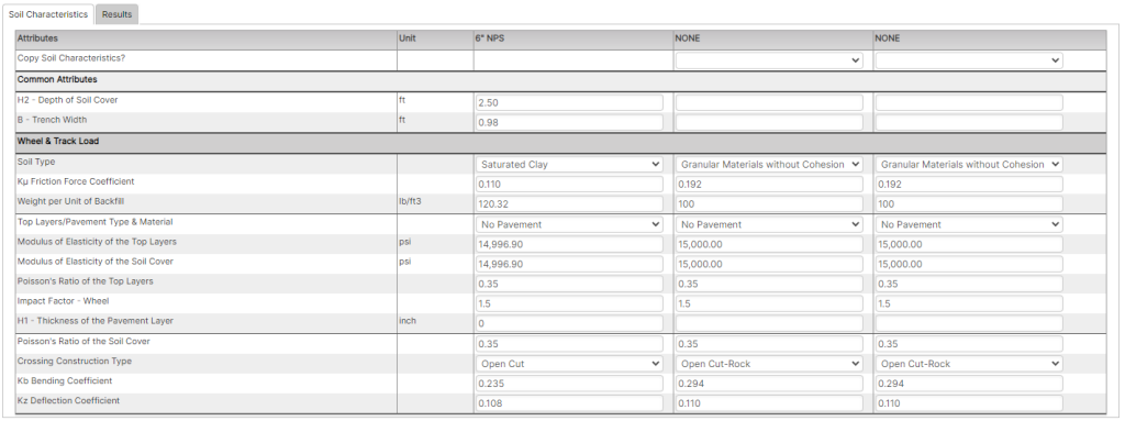
- “Copy Soil Characteristics?” in the Soil Characteristics tab is available when more than one pipe is added and the pipe options are sequential for each column. The functionality of “Copy Soil Characteristics?” is to copy all the soil characteristics data from the previous pipe selected by the user from the drop-down options.

- Clicking on Calculate will display the results for the pipe name – equipment name combinations added by the user.
- Steel Pipe
- Polyethylene Pipe
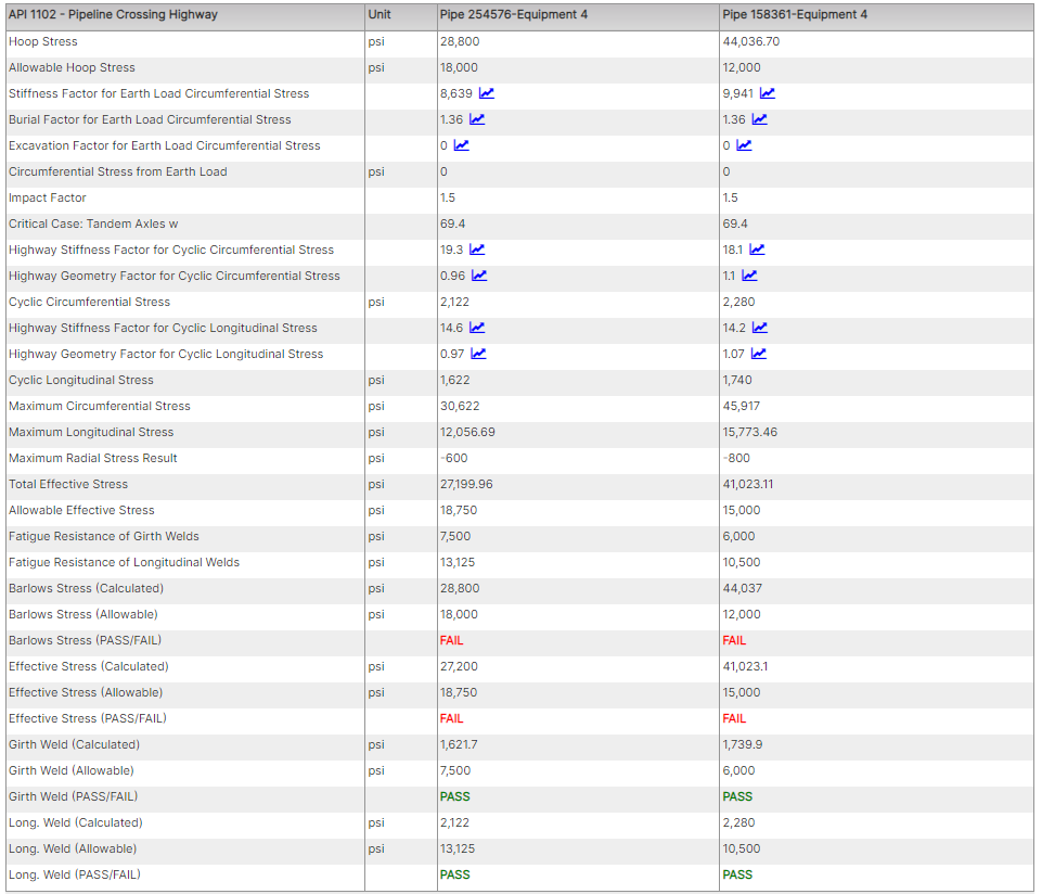
- The results are separated by the equipment added by the user.
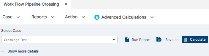
- Clicking on “Run Report” will open the PDF report of the results for the entire analysis.
- Clicking on “Save As” will allow the user to copy a case with a different name.
- Clicking on “Calculate” will run the inputted parameters in the cases.
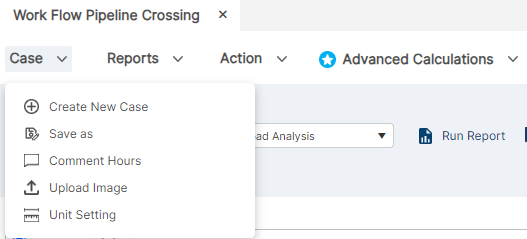
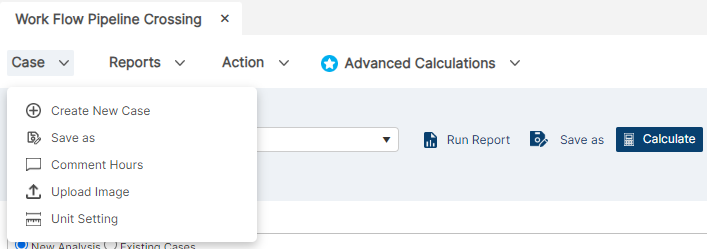
- Clicking on “Case” will reveal a dropdown menu with actions related to the case.
- “Create New Case ” generates a new case file with your parameters.
- “Save As” will allow the user to copy a case with a different name.
- “Comment Hours” will create customizable descriptions in your case.
- “Upload Image” to place image/PDF to follow with report.
- “Unit Setting” will launch a pop-up to select the unit set to be used.
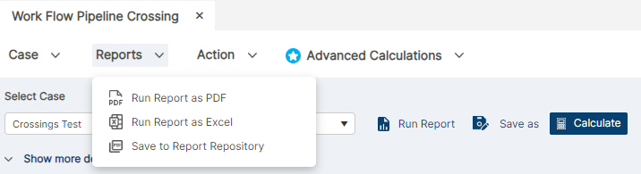
- Clicking on “Reports” will reveal a dropdown menu with actions related to the case.
- “Run Report as PDF” will download a PDF Report of the results for the entire analysis.
- “Run Report as Excel” will download a screenshot of the visible extent of the Workflow widget.
- “Save To Report Repository” will add saved report to repository.
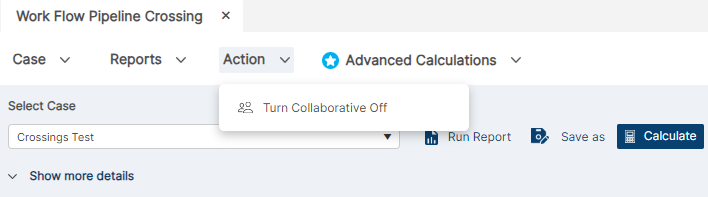
- Clicking on “Reports” will reveal a dropdown menu with actions related to the case.
- “Turn Collaborative” will be able to be turned on/off for others to collaborate and make changes to cases.
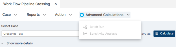
- Clicking on “Reports” will reveal a dropdown menu with actions related to the case.
- “Batch Run” will calculate batches of pipes for reports
- “Sensitivity Analysis” will generate a graphed report and more in depth analysis.
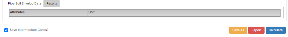
- Click on “Save intermediate Cases?” checkbox and then click on “Save” to save the Workflow Pipeline Crossing case in the respective PLTB – Pipeline Crossing (Liquid/Gas) module. Case name saved in PLTB crossing is as follows – “Workflow case name-pipe name-equipment name-random number.” For example, the number of cases created in individual modules from the workflow widget is the number of equipment added times the number of pipes added (example: 2 wheel load equipment’s (liquid), 1 track load equipment (gas), 2 pipeline crossing highway (liquid) and 2 pipeline crossing railroad (gas) and 2 pipes are added by the user. The total cases created are 14 as listed below:
- Wheel load equipment 1- pipe1 (liquid)
- Wheel load equipment1 – pipe 2 (liquid)
- Wheel load equipment2-pipe1 (liquid)
Wheel load equipment2- pipe2 (liquid) - Track load equioment1-pipe1 (gas)
- Track load equioment1-pipe2 (gas)
- Pipeline crossing highway equipment1-pipe1 (liquid)
- Pipeline crossing highway equipment1-pipe2 (liquid)
- Pipeline crossing highway equipment2-pipe1 (liquid)
- Pipeline crossing highway equipment2-pipe2 (liquid)
- Pipeline crossing railroad equipment1-pipe1 (gas)
- Pipeline crossing railroad equipment1-pipe2 (gas)
- Pipeline crossing railroad equipment2-pipe1 (gas)
- Pipeline crossing railroad equipment2-pipe2 (gas)
- Clicking on “Save As” will allow the user to copy a case with a different name.
- Selecting Existing Case will allow the user to select existing cases from PLTB – Pipeline Crossing (Liquid & Gas) modules via dropdown. When this is selected, equipment, pipe, and soil characteristics data is loaded which can be edited, saved, and calculated.
- Clicking on “Save As” will allow the user to copy a case with a different name.
Workflow (Existing Cases)
Selecting Existing Case will allow the user to select existing cases from PLTB – Pipeline Crossing (Liquid & Gas) modules via dropdown. When this is selected, equipment, pipe and soil characteristics data is loaded which can be edited, saved and calculated.
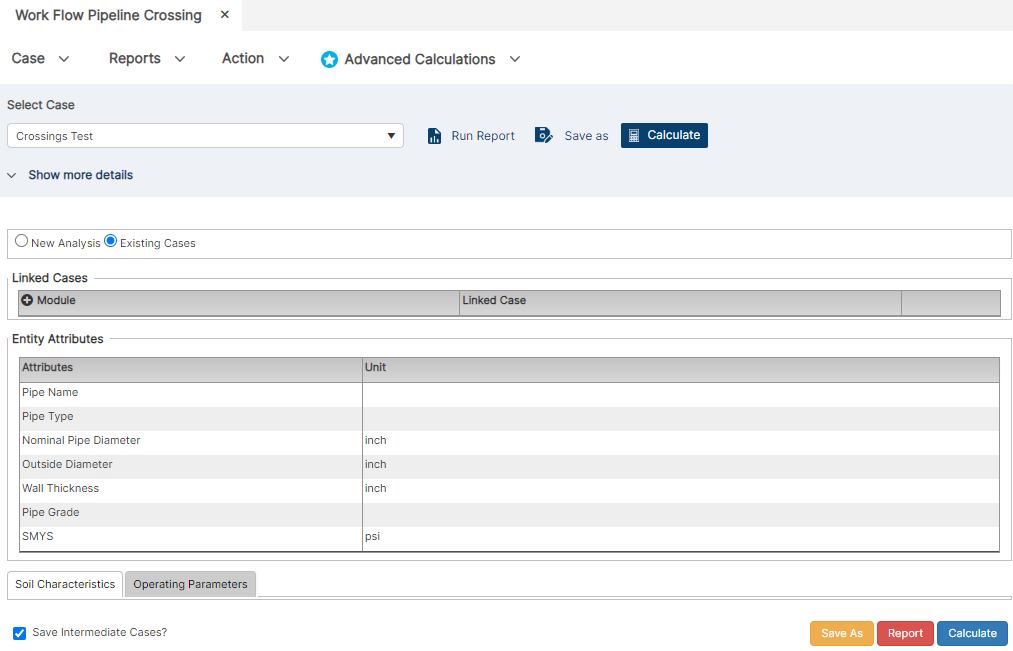
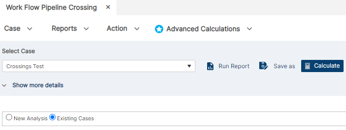
- To create a new workflow based on existing cases, Open Workflow – Pipeline Crossing from the blue ribbon and select the Existing Cases radio button.
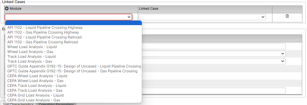
- Click on “Add New Row” icon (blue plus icon) beside “Module” in the Linked Cases section to add a row to select a module from the drop-down.

- The drop-down shows all available/supported PLTB Pipeline Crossing (Liquid & Gas) modules that can be added (Figure 1), while the Linked Case drop-down shows all available cases within any given module selection (Figure 2). Note that once both a Module and Linked Case are selected, the pre-existing case data will pre-populate the Existing Case workflow.
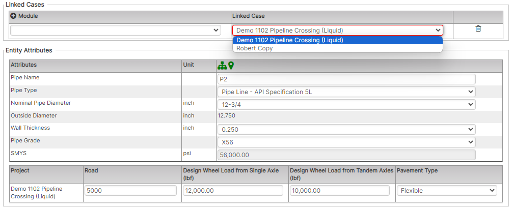
(Data Populates After Linked Case is Selected)
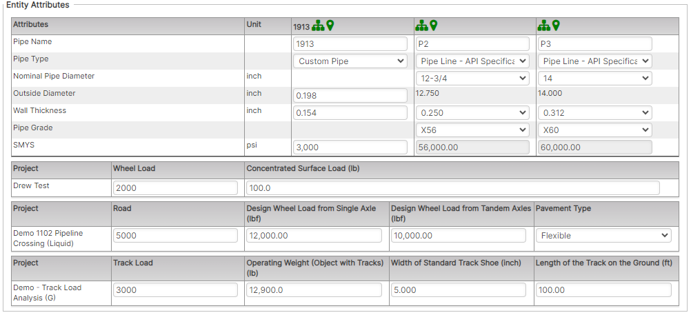
- Repeat steps 2 and 3 above for all cases that are to be linked together in this Existing Case workflow.
- Modify any of the individual case pipe or project equipment-related information in the above fields:
- Modify any Linked Existing Case pre-existing Soil Characteristics:
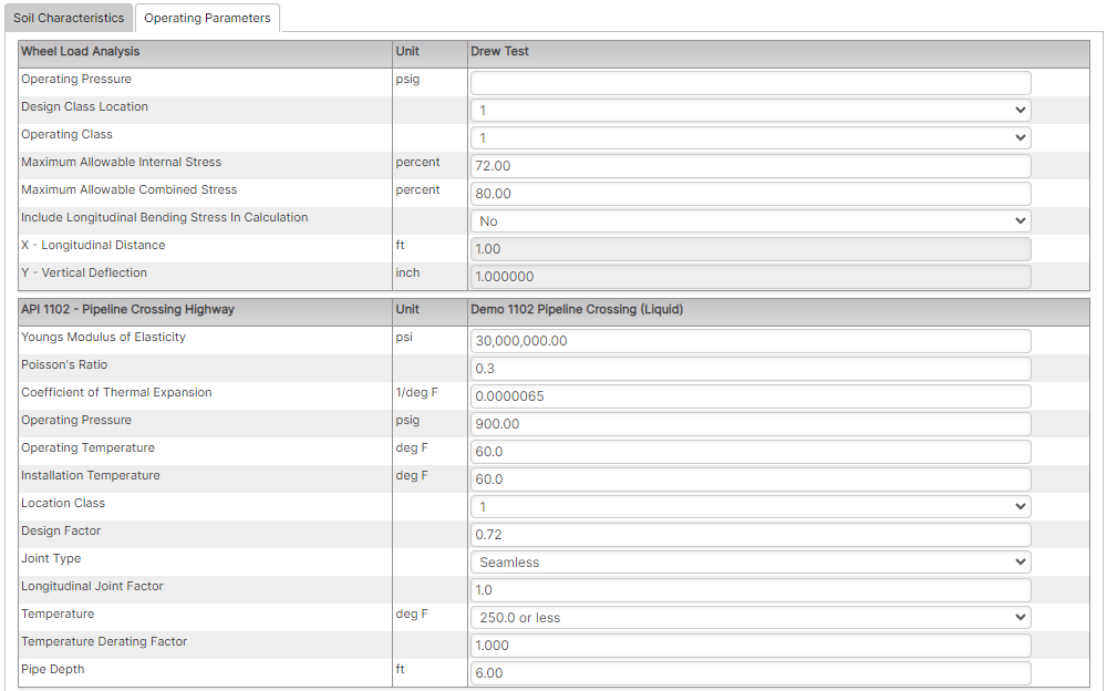
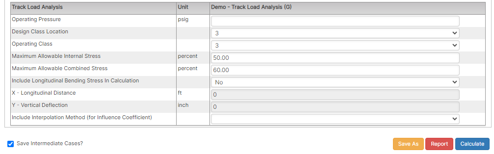
- Modify any Linked Existing Case pre-existing Operating Parameters:
- Once all existing cases have been loaded the steps for reporting, saving, and exporting are the same as the Workflow (New Cases) above.